Applies To:
Show Versions
F5 iWorkflow
- 2.3.0
About F5 and Cisco APIC integration
F5® products integrate with Cisco Application Policy Infrastructure Controller (APIC) using a Device Package. The F5 BIG-IP® Device Package for Cisco APIC downloads from a iWorkflow device, and then is imported into APIC. The file contains:
- A device model, which describes the features and functions available to APIC on the BIG-IP system
- A device script, which implements the features and functions described by the device model
APIC is built with a standard application programming interface (API) used to configure services implemented by integrated vendor devices, such as F5. The F5 BIG-IP device package for Cisco APIC implements the API specific to the semantics of the BIG-IP system.
Using Cisco APIC, a customer can configure tenants, device clusters containing one or two BIG-IP devices, and service graphs. When a service graph is pushed to the BIG-IP system, the F5 BIG-IP Device Package for Cisco APIC running on Cisco APIC uses iApps® to configure all aspects of the supported service.
Each Tenant context is assigned a unique partition on the BIG-IP system, in the form of apic-<APIC Tenant>-<VRF Name>-XXXX, where XXXX is the Tenant ID. Similarly, each Tenant is assigned a random, unique route domain ID. After successfully deploying a service graph on the BIG-IP system, you can log in to the BIG-IP system to view the configuration.
Cisco APIC uses a single admin-level userid and password to configure the BIG-IP system on behalf of all tenants. Tenants are not expected to log in to the BIG-IP system to diagnose issues: that is the responsibility of the provider administrator.
When you are choosing BIG-IP devices to integrate with Cisco APIC, F5 recommends you use dedicated device(s), and not a BIG-IP system that is already being used (or will be used) for another purpose. This is mainly because parts of this configuration, especially the device cluster HA setup, are managed by the device package.
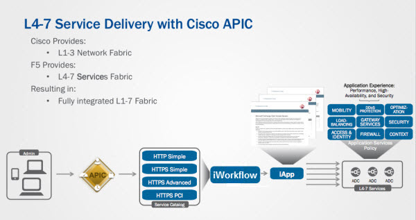
The logical flow between Cisco APIC and the BIG-IP system
- An administrator uses the northbound API or the user interface on APIC for configuration.
- Service graphs created on APIC cause device packages to push network configurations to BIG-IPs and iApp configuration to iWorkflow.
- The APIC API for L4-L7 services is implemented by the F5 device script.
- The device script uses iApp calls to translate the standard APIC API calls into BIG-IP system calls. The iApp configuration is sent to iWorkflow by the device package. iWorkflow then translates this call and implements the service to the BIG-IP.
- Status and information from these calls are packaged and returned to APIC for processing.
APIC-related documentation
- For detailed information about Cisco ACI, see http://www.cisco.com/c/en/us/solutions/data-center-virtualization/application-centric-infrastructure/index.html.
- For detailed information about Cisco APIC, see http://www.cisco.com/c/en/us/products/cloud-systems-management/application-policy-infrastructure-controller-apic/index.html
- For more information about APIC, refer to your Cisco APIC documentation set.
About network topology using the BIG-IP system integrated with Cisco APIC
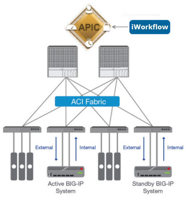
A typical network topology using the BIG-IP® system integrated with Cisco ACI
The internal and external interfaces on the BIG-IP system are connected to leaf nodes in the ACI architecture. Items such as web servers, database engines, and application tiers are also connected to leaf nodes. Spine nodes handle the routing between the BIG-IP system and the various other end points necessary to deliver an application service.
The management port of the BIG-IP system is connected out-of-band to a switch outside of the ACI architecture (not shown in the diagram) to provide management access.
This diagram is not meant to illustrate all possible architectures but rather communicate a typical architecture showing where the BIG-IP system fits into the Cisco ACI architecture.
Version requirements
Make sure your environment meets or exceeds these requirements before you integrate F5® iWorkflow™ with Cisco APIC.
- Cisco APIC and Switch software
- F5 iWorkflow version 2.3.0
Minimum Cisco APIC requirements
Be sure your environment meets or exceeds these requirements before you integrate the F5® iWorkflow™ with Cisco APIC.
- You must have access to an administrator-level account on the Cisco APIC.
- All external network configuration must be complete.
- The Layer 3 networks must be defined and operational.
- The initial configuration of APIC and ACI must be complete. This includes racking and cabling the hardware, powering on the devices, installing the Cisco APIC and Switch version software, configuring the management IP address and verifying that it is reachable.
- The AAA configuration (such as RADIUS or LDAP) must be completed and operational. You might need to create an application EPG to reach external AAA servers to verify the AAA configuration is functioning properly.
- Any APIC tenants, security domains, private network(s), bridge domain(s), and related objects must be configured and operational.
- Any inter-EPG application filters, contracts, and application profiles (if needed) to facilitate traffic flow between EPGs must be created.
- You must have created a management EPG, which is required for APIC to reach the management IP addresses of the BIG-IP® system(s).
- If you are testing multi-tenancy, you must have access to an account assigned to a tenant.
- If you plan on using the BIG-IP Virtual Edition (VE) in your environment, you must have created a Virtual Machine Mobility (VMM) domain and configured vCenter integration.
- If you plan on using a physical BIG-IP appliance in your environment, you must have created a physical domain.
Refer to the Cisco APIC Layer 4 to Layer 7 Services Deployment Guide for specific details about how to configure APIC.
Minimum F5 BIG-IP requirements
Be sure your environment meets or exceeds these requirements before you attempt to integrate the F5® iWorkflow™ with Cisco APIC. Refer to the BIG-IP® system documentation on the F5 technical support site (support.f5.com/kb/en-us/products/big-ip_ltm.html) for specific information about how to configure the BIG-IP system to meet these requirements.
- You must have access to an administrator-level account on the BIG-IP system.
- The BIG-IP system must be running a supported version. Note: For the most current list of compatible versions, refer to the F5 iWorkflow compatibility matrix (K11198324) on support.f5.com.
- The BIG-IP system must be cabled to a leaf switch and powered on (if using an appliance, or started in a VMware environment (if using a Virtual Edition).
- You must have discovered the BIG-IP devices you plan to use with the iWorkflow system.
About configuring the iWorkflow device for a Cisco APIC integration
Some of the tasks you perform to deploy iWorkflow™ in a Cisco APIC environment are performed on the iWorkflow device. You discover devices, create a connector and a custom template, and then export a device package. This device package is the key element of the integration from the Cisco APIC perspective. The parameters and values communicated when you import the package contains the configuration information the Cisco environment needs to perform the integration.
Provisioning the vCMP feature
- Log in to BIG-IP® device with the administrator user name and password.
- On the Main tab, click .
- Verify that all BIG-IP modules are set to None.
- From the vCMP list, select Dedicated.
- Click Submit.
Create a vCMP connector
To enable integration between the vCMP® host and F5 iWorkflow™, you must configure a cloud connector. A cloud connector is a resource that identifies the local or virtual environment in which a tenant deploys applications and, when necessary, adds parameters that are required by third-party cloud providers.
The vCMP connector begins managing the vCMP Host. vCMP guests will be automatically discovered and displayed in the Devices panel as they are created for this vCMP host.
During the automatic discovery of vCMP guests, you may need to enter the user name and password for the vCMP guest in the Devices panel. After you enter the credentials, click Rediscover.
Creating a vCMP guest for Cisco APIC
Before creating a guest on the system, verify that you have provisioned the vCMP feature on the vCMP host.
Deploying a vCMP guest for Cisco APIC
Discovering a BIG-IP guest
Before you can discover a vCMP guest, you must first create and deploy it on the vCMP host.
Discovering a BIG-IP device in your network by its IP address
Adding a Cisco APIC connector
Before you add a Cisco APIC connector, you must discover the F5 devices that you plan to include in your Cisco APIC integration.
To use vCMP® with iWorkflow 2.3.0, you must create the vCMP connectors before you create an APIC connector.
Exporting an iApps template
Importing an iApps template
Creating a customized service template
You must create at least one custom catalog template, based on an iApps® Template, that provides the network settings, levels of services, and so forth, that you expect to see in your APIC environment. You can modify the base template, choosing default values for selected parameters and specifying which parameters can be edited by the tenant. The values specified in the application templates you create are included in the device package that you export to Cisco APIC.
About configuring the Cisco APIC for iWorkflow integration
After you finish configuring iWorkflow™ for integration, there are some tasks to perform in the Cisco APIC environment to complete the integration. You install the device package, create a device cluster, and then create a service graph.
A device cluster is a logical representation of one or more concrete devices acting as a single device. Concrete devices are physical (or virtual) BIG-IP® devices added to the device cluster. For more information, refer to the Cisco APIC documentation.
Installing the F5 BIG-IP device package on Cisco APIC
-
In the right pane, click Import a Device Package.
Importing the Device Package
-
Once the installation is complete, verify the device package is accepted by
APIC.
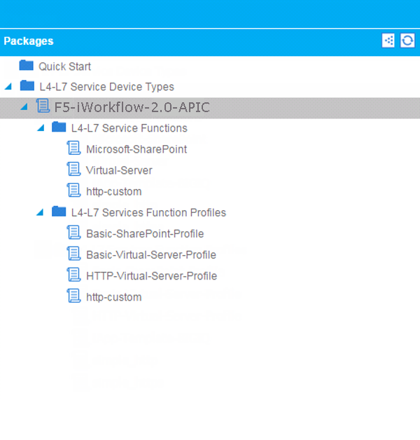
- In the left pane, click L4-L7 Service Device Types to open the folder.
- Click the device service package that you want, such as F5-iWorkflow-2.0, to expand the F5 iWorkflow device package for Cisco APIC.
- Click L4-L7 Service Functions.
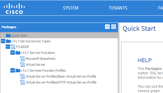
Verifying successful installation of the package
- Confirm that you have specified the tenants for whom you plan to make services available. If you have not, then create and configure those tenants.
- Create and configure the end point groups and bridge domains that your tenants require.
- Create the Physical Domain with associated VLAN and VXLANs name space.
Creating a new chassis type
- On the menu bar, click L4-L7 Services and then click Inventory.
- In the left pane, right-click L4-L7 Chassis Types, and select Create L4-L7 Chassis Type.
- For the Vendor, type F5.
- For the Model, type iWorkflow.
- For the Version, type 2.0-apic.
- For the L4-L7 Service Device Type, select the name of the device package you created for this integration.
- Click Submit.
Creating a chassis manager
Using the chassis manager, you specify the configuration details for the vCMP hosts on which your vCMP guests reside. Cisco APIC needs these details so it can communicate with the guests. When you use multiple vCMP hosts to create a high availability cluster, create a new chassis for each host.
Creating a new device manager type
Creating a new device manager
Creating a device cluster for BIG-IP devices
As part of the iWorkflow™ and Cisco APIC integration, you create an L4-L7 device cluster. Creating the BIG-IP® device cluster using the F5 Device Package tells APIC a number of things about the F5 BIG-IP devices:
- Their network topology
- Access credentials
- IP addresses
- Configuration details
Additionally, when you create the device cluster, you specify all of the configuration details that Cisco APIC needs for the cluster.
Viewing the device cluster you created
- On the menu bar, click TENANTS, and then click the tenant for whom the device cluster was created.
- In the left pane, expand the Tenant folder and then the L4-L7 Services folder.
- Click Device Clusters.
Exporting the device cluster to a tenant
-
Click SUBMIT.
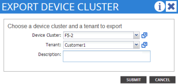
Exporting the device cluster
You should be able to view the device cluster you exported.
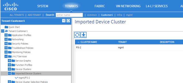
Viewing the device cluster
About service graphs
A service graph is a single listener (iApp) with its associated configuration objects that are required to allow traffic to go through the BIG-IP® system to a destination pool and the nodes in that pool.
The iApp itself is unique, so each service graph is one iApp. You can associate configuration objects and you can share some of those objects between the service graphs (iApps). The iApp port, protocol, and IP address are all unique.
A multigraph means that a iWorkflow system has multiple service graphs that are associated with a single tenant on the iWorkflow device.
Managing SSL certificates and keys
To enhance security, SSL certificates and keys are managed locally in the SSL Certificate List under BIG-IP File Management.
Using the iWorkflow service catalog workflow, when you create a template, you can reference SSL certificates and keys that are stored in the Common partition. You must have Administrator rights to peform this task.
In the following example, the f5.http iApp template is being used to create a new template. It is referencing SSL certificates and keys that are stored in the /Common partition.
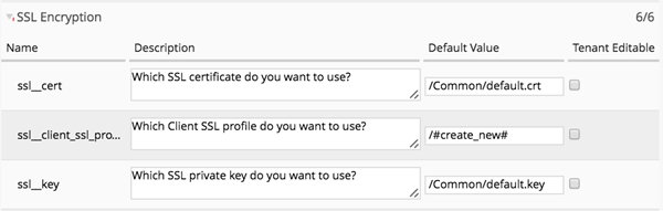
Managing SSL certificates and keys
As Administrator, you have the option to make this field tenant editable, which makes the SSL certificate and key fields visible in the Cisco APIC user interface.
Creating a service graph
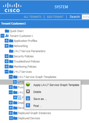
Selecting your service graph for deployment
-
Right-click the service graph you created, and then select Apply
L4-L7 Service Graph Template.
Applying the service graph template
Applying the L4-L7 service graph template
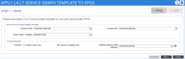
Applying the service graph template to EPGs
If you log in to the iWorkflow™ device and look at the Services panel, you can confirm that the application deployed successfully.
If you log in to one of the BIG-IP® devices and look at the screen, you can confirm that the iApp deployed successfully.


