Applies To:
Show Versions
BIG-IP AAM
- 11.5.10, 11.5.9, 11.5.8, 11.5.7, 11.5.6, 11.5.5, 11.5.4, 11.5.3, 11.5.2, 11.5.1
BIG-IP APM
- 11.5.10, 11.5.9, 11.5.8, 11.5.7, 11.5.6, 11.5.5, 11.5.4, 11.5.3, 11.5.2, 11.5.1
BIG-IP GTM
- 11.5.10, 11.5.9, 11.5.8, 11.5.7, 11.5.6, 11.5.5, 11.5.4, 11.5.3, 11.5.2, 11.5.1
BIG-IP Link Controller
- 11.5.10, 11.5.9, 11.5.8, 11.5.7, 11.5.6, 11.5.5, 11.5.4, 11.5.3, 11.5.2, 11.5.1
BIG-IP Analytics
- 11.5.10, 11.5.9, 11.5.8, 11.5.7, 11.5.6, 11.5.5, 11.5.4, 11.5.3, 11.5.2, 11.5.1
BIG-IP LTM
- 11.5.10, 11.5.9, 11.5.8, 11.5.7, 11.5.6, 11.5.5, 11.5.4, 11.5.3, 11.5.2, 11.5.1
BIG-IP AFM
- 11.5.10, 11.5.9, 11.5.8, 11.5.7, 11.5.6, 11.5.5, 11.5.4, 11.5.3, 11.5.2, 11.5.1
BIG-IP PEM
- 11.5.10, 11.5.9, 11.5.8, 11.5.7, 11.5.6, 11.5.5, 11.5.4, 11.5.3, 11.5.2, 11.5.1
BIG-IP ASM
- 11.5.10, 11.5.9, 11.5.8, 11.5.7, 11.5.6, 11.5.5, 11.5.4, 11.5.3, 11.5.2, 11.5.1
Configuring an EtherIP Tunnel
Overview: Preserving BIG-IP connections during live virtual machine migration
In some network configurations, the BIG-IP® system is configured to send application traffic to destination servers that are implemented as VMware® virtual machines (VMs). These VMs can undergo live migration, using VMware vMotion™ and an iSession™ tunnel, across a wide area network (WAN) to a host in another data center.
To preserve any existing connections between the BIG-IP system and a virtual machine while the virtual machine migrates to another data center, you can create an EtherIP tunnel.
An EtherIP tunnel is an object that you create on each of two BIG-IP systems that sit on either side of a WAN. The EtherIP tunnel uses the industry-standard EtherIP protocol to tunnel Ethernet and IEEE 802.3 media access control (MAC) frames across an IP network. The two EtherIP tunnel objects together form a tunnel that logically connects two data centers. When the application traffic that flows between one of the BIG-IP systems and the VM is routed through the EtherIP tunnel, connections are preserved during and after the VM migration.
After you have configured the BIG-IP system to preserve connections to migrating VMs, you can create a Virtual Location monitor for the pool. A Virtual Location monitor ensures that the BIG-IP system sends connections to a local pool member rather than a remote pool one, when some of the pool members have migrated to a remote data center.
Illustration of EtherIP tunneling in a vMotion environment
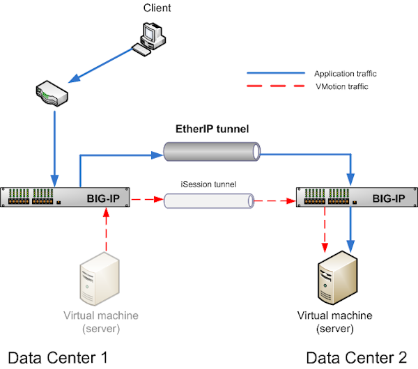
EtherIP tunneling in a vMotion environment
Task summary
Implement an EtherIP tunneling configuration to prevent the BIG-IP® system from dropping existing connections to migrating virtual machines in a vMotion environment. To set up this configuration, you must verify a few prerequisite tasks, as well as create some configuration objects on the BIG-IP system.
Before you begin configuring EtherIP tunneling, verify that these BIG-IP objects and module exist on the BIG-IP system:
- An iSession profile
- This profile creates an iSession tunnel to optimize the live migration of virtual machine servers from one data center to another.
- A load balancing pool
- This pool represents a collection of virtual machines on a host server in the data center.
- A standard TCP or UDP virtual server
- This virtual server load balances application traffic and optimizes vMotion traffic. This virtual server must reference the iSession profile and the load balancing pool.
- The default VLANs
- These VLANs are named external and internal.
- BIG-IP Global Traffic Manager™
- This module directs traffic to the correct BIG-IP® Local Traffic Manager™ virtual server.
Task List
Creating a VLAN
Creating an EtherIP profile
Creating an EtherIP tunnel object
Creating a VLAN group
Creating a self IP address for a VLAN
Creating a self IP for a VLAN group
Creating a Virtual Location monitor
Syncing the BIG-IP configuration to the device group
Implementation result
After you configure EtherIP tunneling on the BIG-IP system, you must perform the same configuration procedure on the BIG-IP system in the remote data center to fully establish the EtherIP tunnel.
After the tunnel is established, the BIG-IP system preserves any open connections to migrating (or migrated) virtual machine servers.


