Manual Chapter : Platform Maintenance

Applies To:

Show Versions Show Versions
Manual Chapter

Platform Maintenance

About maintaining the platform

The VIPRION® 4400 Series platform contains several components that you can replace individually without exchanging the entire system. This platform contains these replaceable components:

  • AC power supply
  • DC power supply
  • Fan tray
  • Storage drive assembly
    Note: Applies only to the B4300 blade with hard disk drive (HDD).
  • Front bezel (with LCD component)
  • Blades

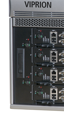
About AC power supplies

The VIPRION® 4400 Series platform supports up to four hot swappable power supplies. These power supplies can operate in one of two modes: 120V and 220V, depending on the power source to which the power supplies are connected.

The platform supports both symmetric and asymmetric power redundancy. Symmetric redundancy (2 * N) requires an even number of power supplies, with half supplied by one power feed and half by another. If one power feed fails, the system is unaffected because the remaining supplies are sufficient for the entire load. With asymmetric redundancy (n + 1), it is not possible to split the supplies evenly between the power feeds. As a result, if one power feed fails, the entire system can go down. In either type of redundancy, if a single power supply fails, the system is unaffected by the loss of a single supply.

Partially-removed power supply

A power supply partially removed from the platform

CAUTION:
Running without all power supplies installed in the platform can affect cooling and electromagnetic interference (EMI). If a power supply fails, you can leave it installed in the chassis and remove the power cord; the system, however, will continue to log errors. If you need to run the unit without all power supplies installed, you must install a blank supply bracket into any empty power supply slots. The blank supply bracket is required to maintain proper airflow in the system.
CAUTION:
The power socket outlet should be installed near the equipment and easily accessible.
Important: This product is sensitive to electrostatic discharge (ESD). F5® recommends that you use proper ESD grounding procedures and equipment when you install or maintain the unit.
Note: Depending on the model and revision type of the power supply, you might need either a Phillips or a slotted screwdriver to replace the power supply.

Installing an AC power supply

If a power supply is already installed in the bay where you are installing the replacement supply, disconnect the AC power cord for the corresponding power supply from the back of the chassis and remove the existing supply from the chassis.
In the event of a power supply failure, you can replace an AC power supply without powering down the system, provided that there are still enough power supplies to equal one less than the number of running blades. For example, if the chassis has three blades, you can replace a power supply, as long as the platform has at least two power supplies operating during the replacement process.
  1. Using the indentations on either side of the LCD component, remove the front bezel from the chassis.
    With the front bezel removed, you can see the power supplies and the available power supply bays.
  2. Remove the existing supply, if one is installed.
  3. Slide the new power supply into the empty power supply bay.
  4. Lower the power supply eject lever to fully seat the power supply in its bay.
  5. Secure the power supply in its bay by tightening the screw in the middle of the power supply eject lever.
    Note: The screw that holds the ejector handle in place is captive and cannot be removed from the assembly.
  6. Attach the power cord for the new power supply to the back of the unit, using the corresponding power supply connector.
  7. Replace the front bezel.

About DC power supplies

The VIPRION® 4400 Series platform supports up to four hot swappable DC power supplies.

You can install a DC power supply without powering down the system, provided that there are still enough power supplies to equal one less than the number of running blades. For example, if the chassis has three blades, you can replace a power supply, as long as the platform has at least two power supplies operating during the replacement process.

The platform supports both symmetric and asymmetric power redundancy. Symmetric redundancy (2 * N) requires an even number of power supplies, with half supplied by one power feed and half by another. If one power feed fails, the system is unaffected because the remaining supplies are sufficient for the entire load. With asymmetric redundancy (n + 1), it is not possible to split the supplies evenly between the power feeds. As a result, if one power feed fails, the whole system can go down. In either type of redundancy, if a single power supply fails, the system is unaffected by the loss of a single supply.

The DC power supply does not have an on/off switch. You can control the power from the rack switch or the DC power source.

DC power supply

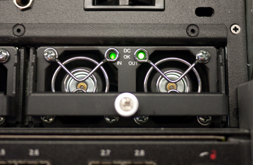
VIPRION 4400 Series DC power supply

CAUTION:
Running without all power supplies installed in the platform can affect cooling and electromagnetic interference (EMI). If a power supply fails, you can leave it installed in the chassis and remove the power cord; the system, however, will continue to log errors. If you need to run the unit without all power supplies installed, you must install a blank supply bracket into any empty power supply slots. The blank supply bracket is required to maintain proper airflow in the system.
CAUTION:
Before you begin to work with one of these platforms, refer to the DC-powered equipment environmental warnings for this platform and review any safety requirements for the facilities where the DC-powered platforms will be installed.
Important: This product is sensitive to electrostatic discharge (ESD). F5® recommends that you use proper ESD grounding procedures and equipment when you install or maintain the unit.
Important: The platform must be installed in a RESTRICTED ACCESS LOCATION, such as a central office or customer premises environment.
Note: All copper grounding cable must meet all appropriate safety standards and local electric codes.
Note: You should coat bare conductors with an appropriate antioxidant compound before you make crimp connections. You should bring all unplated connectors, braided strap, and bus bars to a bright finish and then coat them with an antioxidant before you connect them.
Note: The platform must be grounded to a common bonding network (CBN).
Note: The battery return terminals on the platform are in an isolated DC return (DC-I) configuration.

Installing a DC power supply
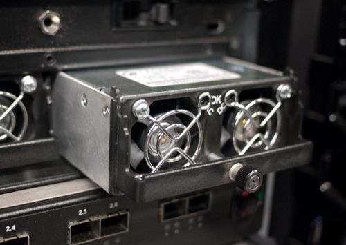
If a power supply is already installed in the bay where you are installing the replacement supply, disconnect the DC terminal block for the corresponding power supply from the back of the chassis and remove the existing supply from the chassis.
In the event of a power supply failure, you can replace a DC power supply without powering down the system, provided that there are still enough power supplies to equal one less than the number of running blades. For example, if the chassis has three blades, you can replace a power supply, as long as the platform has at least two power supplies operating during the replacement process.
Note: You should wait at least five seconds before re-inserting a power supply that you have removed. Otherwise, the LEDs for the power supply might remain OFF, and the system will report that power supply as being in a down state.
  1. Using the indentations on either side of the LCD component, remove the front bezel from the chassis.
    With the front bezel removed, you can see the power supplies and the available power supply bays.
  2. Remove the existing supply, if one is installed.
  3. Slide the new power supply into the empty power supply bay.
  4. Lower the power supply eject lever to fully seat the power supply in its bay.
  5. Secure the power supply in its bay by tightening the screw in the middle of the power supply eject lever.
    Note: The screw that holds the ejector handle in place is captive and cannot be removed from the assembly.
  6. Connect the DC terminal for the new power supply to the back of the unit, using the corresponding power supply connector.
  7. Replace the front bezel.

About the fan tray

The VIPRION® 4400 Series platform has a removable fan tray that is designed to maintain airflow throughout the chassis. You can change or replace the fan tray as part of the routine maintenance of the unit, or in the event of a fan failure. The fans in the fan tray run constantly while the unit is on. Over time, the fans can wear out, requiring you to replace the fan tray.

Important: This product is sensitive to electrostatic discharge (ESD). F5® recommends that you use proper ESD grounding procedures and equipment when you install or maintain the unit.
An example of a fan tray in a platform

Fan tray in the platform

Replacing the fan tray

You can replace the fan tray as part of routine maintenance or in the event of a fan tray failure. You do not need special tools to replace the fan tray. You do not need to power down the unit when replacing the fan tray; however, F5® highly recommends that you do not leave the unit operating without a fan tray for longer than 30 seconds.
CAUTION:
Operating the unit without a fan tray for more than 30 seconds might cause permanent damage.
  1. Turn the compression screws on the fan tray, until the locking indicator changes color from green (locked) to red (unlocked).
  2. Stand at the front of the platform and locate the ejector handle on the fan tray.
    The ejector handle is located in the middle of the fan tray, which is located on the left side of the chassis.
  3. Extend the fan tray handle by pressing the top portion of the handle into the unit.
    The handle extends, revealing a ring that you can use to extract the fan tray.
  4. Grasp the ejector handle and remove the fan tray from the chassis by pulling straight toward you.
  5. Place the new fan tray into the fan tray bay.
  6. Push the fan tray into the chassis until it is seated firmly in the fan tray bay.
    Once seated, the fan tray automatically powers up and begins circulating air through the chassis.
    Important: Use only the fan tray handle to seat the fan tray in the chassis. Using the edges of the fan tray could result in pinched fingers, as a fully-seated fan tray is nearly flush with the other chassis components.

About the storage drives

By default, VIPRION® B4000 blades contain one storage drive. You can remove the drive from the blade only if your company's security requirements necessitate it when performing a Return Material Authorization (RMA) on the platform.

Important: F5® supports replacement of hard disk drives (HDD) only.
Important: This product is sensitive to electrostatic discharge (ESD). F5® recommends that you use proper ESD grounding procedures and equipment when you install or maintain the unit.

Replacing a storage drive assembly on a B4300 blade

You can change or replace a drive assembly in a VIPRION® B4300 Series blade as part of the routine maintenance of the unit or in the event of a drive failure.
  1. Disconnect all cables and remove any optical modules from the blade that contains the drive assembly to be replaced.
  2. Remove the blade from the chassis.
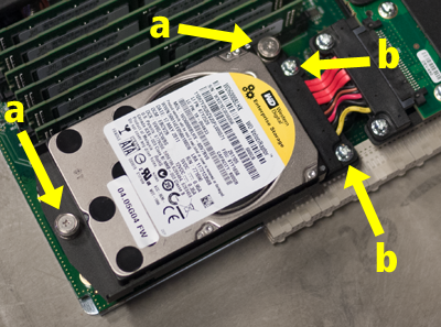
  3. Remove the existing drive assembly, if one is installed:
    1. Loosen the drive assembly screws (a) by turning them counterclockwise with a Phillips screwdriver, if necessary.
      Note: These screws are captive and cannot be removed from the assembly.
      Removing old drive
    2. Remove the SAS cable assembly screws (b) by turning them counterclockwise with a Phillips screwdriver.
    3. Grasp the drive assembly screw on the end, lift the drive assembly slightly, and then pull straight out to remove the drive assembly from the blade.
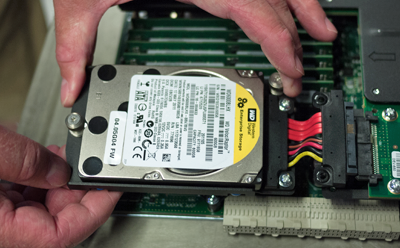
  4. Slide the new drive assembly into the bay and connect it to the SAS cable assembly.
    Install new drive
  5. Tighten all screws into place using 4 inch-pounds (0.45 Newton-meters) of torque.
    The drive assembly is connected to the system when you tighten all screws completely.
  6. Slide the blade back into the chassis.

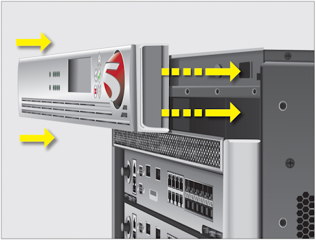
About the front bezel (with LCD component)

The LCD component on the front bezel enables you to access several functions associated with the platform, such as configuring the management port for the system.

Replacing the front bezel

You can replace the front bezel in the unlikely event of an LCD component failure. You do not need special tools to replace the front bezel.
  1. Remove the original front bezel by grasping the bezel on either side, using the indentations provided.
    Note: Failure to use the indentations could result in pinched fingers.
  2. Pick up the replacement front bezel using the indentations provided.
  3. Align the guide pins on the bezel to the corresponding holes in the chassis.
    Replacing the front bezel