Applies To:
Show Versions
BIG-IP LTM
- 11.6.5, 11.6.4, 11.6.3, 11.6.2, 11.6.1
Installing a BIG-IP System Without Changing the IP Network
Overview: Installing a BIG-IP system without changing the IP network
A combination of several features of the BIG-IP®system makes it possible for you to place a BIG-IP system in a network without changing the existing IP network. The following illustration shows the data center topology before you add the BIG-IP system. The data center has one LAN, with one IP network, 10.0.0.0. The data center has one router to the Internet, two web servers, and a back-end mail server.
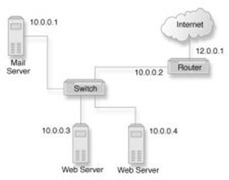
Data center example before adding a BIG-IP system
The existing data center structure does not support load balancing or high availability. The following illustration shows an example of the data center topology after you add the BIG-IP system.
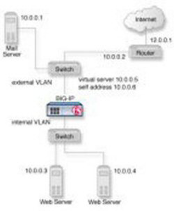
Data center example after adding a BIG-IP system
Task summary
To configure the BIG-IP® system for this implementation, you must perform a few key tasks. The example shown in the illustration is based on the use of the default internal and external VLAN configuration with self IP addresses on each of the VLANs that are on the same IP network on which you are installing the BIG-IP system.
Task list
Removing the self IP addresses from the default VLANs
- On the Main tab, click .
- Select the check box for each IP address and VLAN that you want to delete.
- Click Delete.
- Click Delete.


