Applies To:
Show Versions
BIG-IP LTM
- 11.5.10, 11.5.9, 11.5.8, 11.5.7, 11.5.6, 11.5.5, 11.5.4, 11.5.3, 11.5.2, 11.5.1
Deploying an IPv6 Network using 6rd
Overview: 6rd configuration on BIG-IP systems
The 6rd (rapid deployment) feature is a solution to the IPv6 address transition. It provides a stateless protocol mechanism for tunneling IPv6 traffic from the IPv6 Internet over a service provider's (SP's) IPv4 network to the customer's IPv6 networks. As specified in RFC5969, 6rd uses an SP's own IPv6 address prefix rather than the well-known IPV6 in IPv4 prefix (2002::/16), which means that the operational domain of 6rd is limited to the SP network, and is under the SP's control.
Fully compliant with RFC5969, the BIG-IP® system supports the border relay (BR) functionality by automatically mapping the tunnel's IPv4 address at the customer premises to IPv6 address spaces using the 6rd domain configuration information. Using a BIG-IP system, an SP can deploy a single 6rd domain or multiple 6rd domains. When supporting multiple 6rd domains, a separate tunnel is required to accommodate each 6rd domain, which is specified in the associated 6rd tunnel profile.
When you deploy 6rd using a BIG-IP system as the BR device, you need to create 6rd tunnels using wildcard remote addresses. This implementation documents the configuration of a BIG-IP device as a BR device.
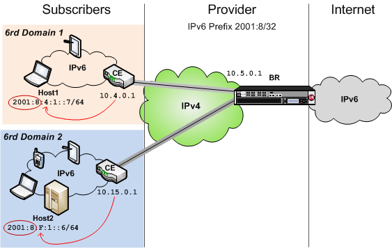
Example of a 6rd configuration
This table shows examples of 6rd parameter values, based on the illustration. You set these values in the v6rd profile you create.
| Setting | Value |
|---|---|
| IPv4 Prefix | 10 |
| IPv4 Prefix Length | 8 |
| IPv6 Prefix | 2001:8:4:1 |
| IPv6 Prefix Length | 64 |
Task summary
Before you configure a 6rd network, ensure that you have licensed and provisioned CGNAT on the BIG-IP® system. Also, the BIG-IP system must have an IPv6 address and an IPv6 default gateway.


