Applies To:
Show Versions
BIG-IP LTM
- 13.1.0, 13.0.1, 13.0.0, 12.1.3, 12.1.2, 12.1.1, 12.1.0
Migrating MBLB Functionality to MRF Functionality
Introduction to MBLB-to-MRF Migration
Introduction
The BIG-IP® system supports client-server protocols (for example, HTTP) and is optimized to manage large numbers of connections, where each connection provides a communication between one client and one server. In this environment, the client always initiates requests and the server always provides responses. A single load balance sequence selects the server from the virtual server’s pool and, for the life of the connection, messages flow between the client and server. When the transaction completes, the connection closes and a new connection can be opened for the next transaction.
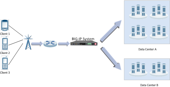
An example service provider network configuration
MBLB functionality
Message based load balancing (MBLB) functionality enables a BIG-IP system to load balance traffic for messaged-based protocols. An MBLB proxy supports message-based protocols by making a load-balance decision for each message. Once the request is forwarded to the selected server, the server-side connection is removed from the client-side connection to allow the next request to be directed to other servers, if required. MBLB proxy maintains an association table, which stores the relationship between the client-side connection and all of the server-side connections created. When a response is received from a server, the association table is used to locate the originator of the request, enabling the response to be forwarded to that client.
MRF functionality
Message routing framework (MRF) functionality provides protocol-independent L7 peer applications, which operate independently from the underlying connection-oriented full proxy. Each protocol implementation of MRF provides a protocol-specific route table, identifying the optimum route for a message as determined by the message's attributes. Each request and response message route is derived from the message's attributes. Associations between client-side and server-side connections are no longer required. Any connection can originate a request or a response, and any connection can provide the destination for a request or a response. MRF maintains a table of all connections to each peer. Based on a configuration, a new connection can be created or a previous connection reused when forwarding a message to a peer (even when the connection exists on a different TMM).
You can migrate message based protocols from MBLB functionality to MRF functionality, as described in the following table.
| BIG-IP software | Supported MRF functionality |
|---|---|
| Version 11.5 | Generic Message protocol. |
| Version 11.6 | SIP load balancing. |
| Version 12.0 | Diameter load balancing. |
Benefits of MRF functionality
Message routing framework (MRF) functionality provides significant benefits compared to message-based load balancing (MBLB) functionality.
Standards support
- Diameter. MRF Diameter routes all messages through a single connection between the BIG-IP system and its peer. It responds to a capabilities exchange as a Diameter node with its own configurable identity and supported applications.
- SIP. MRF SIP identifies and fails many of the illegal messages defined in the SIP torture test that is described in RFC4475. It implements loop and maximum forwarding detection functionality.
Use cases without iRules
MRF functionality performs operations for many use cases without requiring iRules®.
Reuse of existing connections
MRF functionality maintains a table of all open connections to peers. If a message is routed to a peer, it can send the message to that peer by means of an existing connection.
If a connection mode is per-peer, then all Traffic Management Microkernels (TMMs) use the same connection, allowing support of protocols like Diameter that specify that a single connection must exist between two peers.
The router profile that is attached to the virtual server specifies the router instance to which it belongs. The router instance owns the table of open connections. All virtual servers that share the same routing instance can share the same connections. The connection table holds all open connections, including client-side (peer-initiated) and server-side (BIG-IP system initiated) connections.
Routes
All protocols that implement MRF allow you to add protocol-specific static routes to the router instance, controlling how messages are forwarded. The protocol implementation specifies the attributes to match against the message, determining the best route for forwarding the message.
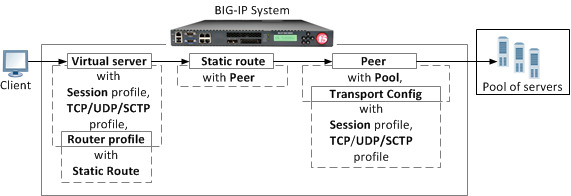
A route can contain a list of peers. A peer contains both a pool and a transport configuration, which allows a route to contain a list of servers that can require different connection parameters. A peer-selection mode specifies the mode for selecting peers from the peer list: sequential or ratio.
- Sequential peer-selection mode. The first peer is selected, unless all of its pool members are marked as down.
- Ratio peer-selection mode. The ratio field for each peer is used to calculate the relative probability of that peer's selection.
Each peer can contain a pool and a transport configuration, which allows each peer in a peer list to use different settings to create an outgoing connection. The peer also specifies the connection mode and number of connections, which determine how connections to the peer are reused.
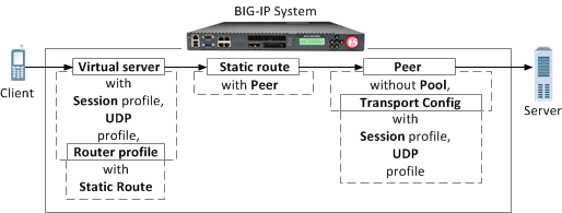
If no pool is specified, the local IP address and port of the originating connection for the message being routed are used as the remote IP and port of the outgoing connection.
If no transport configuration is specified, the parameters of the incoming connection are used to create the outgoing connection. A transport configuration specifies the parameters for an outgoing connection, such as the profiles used, source-address translation, and iRule scripts.
iRule variables
Because the incoming connection and outgoing connection of a message are never associated, and can exist on different TMMs, MRF provides a new method for sharing iRule variables. MRF provides new iRule commands to deliver iRule variables with the message to the outgoing connection.
Automatic response routing
MRF protocol implementations can route response messages back to the originating connection of the request.
Rule routing
MRF introduces iRule commands to route a message to a specific connection or peer.
Persistence
MRF records both endpoints of a session, which permits persistence for subsequent messages in the session, routing them through existing connections or new connections, as required.
The configuration of the persistence record’s key is protocol-specific, and the setting is now a function of the protocol profile. Each virtual server contains a session profile. Because multiple virtual servers can share the same router instance, and each virtual server can be configured with a different protocol profile, the actual keys used for each session can be different, depending on the origination of the message.
MRF SIP load balancing
The Session Initiation Protocol (SIP) operation mode, specifically load balancing, comprises the Message Routing Framework (MRF) Session Initiation Protocol (SIP) use case. You can configure an operation mode in the SIP Router profile. All virtual servers that share the same router profile instance use the same operation mode.
When configured for load balancing, the BIG-IP® system processes and delivers SIP control messages to a SIP endpoint. Note that the BIG-IP system does not manage SIP media flows in a load balancing configuration. A configurable persistence table stores routing and load balancing decisions. No additional state is maintained. SIP media flows travel by means of a different path, or are managed by components other than the SIP control messages.
In the default configuration, the BIG-IP system inserts a Via header into the message used by the recipient, for routing the response message. This Via header includes an encrypted branch parameter, containing the details of the originating connection, and the persistence key. When the BIG-IP system receives a response message, it removes the topmost Via header, decrypts its branch attribute, and uses that attribute to set the next hop of the message to the originating flow. This allows the response message to avoid routing and, instead, get forwarded directly to the originator of the request. If the originating connection has been closed, SIP functionality uses the next topmost Via attribute from the message, and routes the message to the provided IP address and port. No other attributes of the SIP header and Session Description Protocol (SDP) payload are modified in a SIP load balancing operation mode.
You can use a SIP Load Balancing operation mode for multiple use cases. A BIG-IP system can combine multiple use cases, as necessary.
MRF SIP load balancing configuration
MRF SIP load balancing description
SIP load balancing allows a group (or groups) of SIP servers to act as a single SIP device. The BIG-IP® system configures the SIP endpoint with the address of the virtual server representing the group of servers. Because SIP endpoints route media between themselves, the SIP servers do not use media flows. The BIG-IP system can also configure persistence to deliver subsequent control messages to the same proxy server.
An MRF SIP load balancing configuration
The following examples provide a comparison between a message-based load balancing (MBLB) configuration and a message routing framework (MRF) configuration.
An MBLB iRules load balancing configuration example
ltm persistence sip my_persist {
    sip-info Call-ID
}
ltm virtual sip_mlb {
    destination 10.10.10.50:5060
    profiles { udp sip }
    persist { my_persist }
    pool sip_pool
    source-address-translation { type automap }
}
An MRF iRules load balancing configuration example
ltm message-routing sip profile session my_session {
    persistence {
        persist-type session
        persist-key Call-ID
    }
}
ltm message-routing sip transport-config my_tc {
    profiles { udp my_session }
    source-address-translation { type automap }
}
ltm message-routing sip peer default_peer { transport { type config name my_tc } pool sip_pool }
ltm message-routing sip route default_route { peers { default_peer } }
ltm message-routing sip profile router my_router { routes { default_route } }
ltm virtual sip_lb_mrf {
    destination 10.10.10.55:5060
    profiles {
        udp
        my_session
        my_router
    }
}
Source address translation can hide the internal address of the originating SIP endpoint. MRF SIP functionality does not automatically rewrite attributes in the SIP header in the load balancing operation mode. Consequently, the URI, contact address, and received Via attribute in the SIP header contains the untranslated address.
The BIG-IP system routes response messages by using the Via attribute inserted into the request message. This header contains an encrypted branch attribute that contains the ID of the originating connection. If the originating connection closed before the response message is received, the BIG-IP system uses the next Via attribute in the header to route the response to the originating device.
MRF SIP forwarding configuration
MRF SIP forwarding description
A Session Initiation Protocol (SIP) forwarding configuration receives a message on one VLAN and forwards it to another VLAN. This configuration is often used with SIP load balancing to allow the proxy server to invite a SIP endpoint to a call that exists on an internal network. In the forwarding use case, the originating device knows the address of the destination device and the BIG-IP® system's only role is to forward the message to the destination.
The BIG-IP system does not manage media in a SIP load balancing operation mode. If media is required to pass through the BIG-IP system, a forwarding generic User Datagram Protocol (UDP) forwarding virtual server is required.
An MRF SIP forwarding example configuration
The following examples provide a comparison between a message-based load balancing (MBLB) configuration and a message routing framework (MRF) configuration.
An MBLB iRules forwarding configuration example
ltm virtual sip_fw_mlb {
    destination 0.0.0.0:5060
    profiles {
        udp
        sip
    }
    ip-forward
}
An MRF iRules forwarding configuration example
ltm message-routing sip transport-config my_tc {
    profiles {
        udp
        sipsession
    }
}
# a peer without a pool will forward the message
ltm message-routing sip peer default_fw_peer {
     transport-config my_tc
}
ltm message-routing sip route default_fw_route {
    peers {
        default_fw_peer
    }
    virtual-server sip_fw_mrf
}
ltm message-routing sip profile router my_router {
    routes { default_fw_route }
}
ltm virtual sip_fw_mrf {
    destination 0.0.0.0:5060
    profiles {
        udp
        sipsession
        my_router
    }
}
Source address translation can hide the internal address of the originating SIP endpoint. MRF SIP functionality does not automatically rewrite attributes in the SIP header in the load balancing operation mode. Consequently, the URI, contact address, and received Via attribute in the SIP header can contain the untranslated address.
The BIG-IP system routes response messages by using the Via attribute inserted into the request message. This header contains an encrypted branch attribute that contains the ID of the originating connection. If the originating connection closed before the response message is received, the BIG-IP system uses the next Via attribute in the header to route the response to the originating device.
MRF SIP routing configuration
MRF SIP routing description
SIP routing allows the BIG-IP® system to deliver messages to different endpoints, based on attributes of the message. The message routing framework (MRF) SIP implementation can route a message based on the message's request-uri, from-url, to-uri, and the originating virtual server. You can use an iRule script to route messages based on other attributes of the saved state.
The BIG-IP system does not manage media in a SIP load balancing operation mode. If media is required to pass through the BIG-IP system, MRF SIP ALG can be used or a forwarding generic UDP forwarding virtual server.
An MRF SIP routing configuration example
Source address translation can hide the internal address of the originating SIP endpoint. MRF SIP functionality does not automatically rewrite attributes in the SIP header in the load balancing operation mode. Consequently, the URI, contact address, and received Via attribute in the SIP header can contain the untranslated address.
The BIG-IP system routes response messages by using the Via attribute inserted into the request message. This header contains an encrypted branch attribute that contains the ID of the originating connection. If the originating closed before the response message is received, the BIG-IP system uses the next Via attribute in the header to route the response to the originating device.
The following examples show a comparison between a message-based load balancing (MBLB) configuration and a message routing framework (MRF) configuration.
An MBLB iRules routing configuration example
rule sip_route_rule {
when SIP_REQUEST {
  if { [SIP::header value from] ends_with “@f5.com } then {
    if ( [SIP::header value to] ends_with “@f5.com) } then {
LB::snat none
      LB::select
      pool default_pool
    }
  }
if {[SIP::header value from] equals “spammer@domain.com” } then {
   SIP::respond 401 “cannot route message"
}
}
}
ltm persistence sip my_persist { sip-info Call-ID }

 ltm virtual sip_int_mlb { destination 10.20.30.40:5060 profiles { udp sip } persist { my_persist } source-address-translation { type automap } pool default_pool rules { sip_route_rule } }

ltm virtual sip_int_mlb { destination 0.0.0.0:5060 profiles { udp sip } persist { my_persist } rules {sip_route_rule} ip_forward}
An MRF iRules routing configuration example
ltm message-routing sip transport-config my_tc { profiles { udp sipsession } }
ltm message-routing sip transport-config my_snat_tc { profiles { udp sipsession } souce_address_translation { type automap} }
ltm message-routing sip peer default_peer { transport { type config name my_snat_tc } pool default_pool }
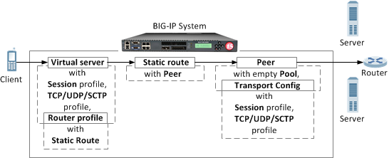
# routing to an empty pool causes an un-routable error to be returned to the originator
ltm message-routing sip peer blackhole_peer { transport {type config } pool empty_pool }
# a peer without a pool will forward the message
ltm message-routing sip peer forward_peer { transport { type config name my_tc } }
ltm message-routing sip peer internal_peer { transport { type config name my_tc } pool internal_pool }
ltm message-routing sip route default_route { peers { default_peer } }
# this will try the first peer unless all pool members are down. Note the first peer does not use SNAT but the second does
ltm message-routing sip route internal_route from-url *@f5.com to-uri *@f5.com peers { internal_peer default_peer }
ltm message-routing sip route blackhole_route from-url spammer@domain.com peers { blackhole_peer }
ltm message-routing sip route forward_route { virtual sip_ext_mr peers { forward_peer } }
ltm message-routing sip profile router { routes { default_route internal_route blackhole_route forward_route } }
ltm virtual sip_int_mrf { destination 10.20.30.40:5060 profiles { udp sipsession my_router } }
ltm virtual sip_ext_mrf { destination 0.0.0.0:5060 profiles { udp sipsession my_router } }
MRF Diameter load balancing
MRF Diameter load balancing configuration
MRF Diameter load balancing description
Diameter load balancing provides capacity scaling and high availability for Diameter signaling servers. Load balancing functionality steers Diameter signaling traffic to a pool of servers, based on static Diameter routes, distributing the load across pool members. Diameter Attribute Value Pair (AVP) parameters (SESSION-ID by default) determine load balancing persistence. Last hop information, which the BIG-IP® system saves on the egress Traffic Management Microkernel (TMM), defines the response routing, which skips the route lookup for response messages.
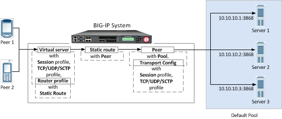
An MRF Diameter load balancing configuration
The following examples provide a comparison between a message-based load balancing (MBLB) configuration and a message routing framework (MRF) configuration.
A common iRules load balancing configuration example
ltm pool default_pool {
    load-balancing-mode round-robin
    members {
        10.10.10.1:diameter {
            address 10.10.10.1
        }
        10.10.10.2:diameter {
            address 10.10.10.2
        }
        10.10.10.3:diameter {
            address 10.10.10.3
        }
    }
}
An MBLB iRules load balancing configuration example
ltm virtual diameter-lb {
    destination 10.20.10.100:3868
    mask 255.255.255.255
    ip-protocol tcp
    pool default_pool
    profiles {
        tcp
        mblb
        diameter
    }
    rules {
        save_conections
    }
}
ltm rule save_conections {
    when LB_FAILED {
        if { [active_members [LB::server pool]] > 0 } {
            LB::reselect pool [LB::server pool]
        }
    }
}
An MRF iRules load balancing configuration example
ltm virtual diameter-lb {
    destination 10.20.10.100:3868
    mask 255.255.255.255
    ip-protocol tcp
    pool none
    profiles {
       tcp
       diametersession
       diameter-router-lb
    }
}
ltm message-routing diameter peer default-peer {
    pool default-pool
}
ltm message-routing diameter route default-route {
    peers { default-peer }
}
ltm message-routing diameter profile router diameter-router-lb {
    routes { default-route }
}
MRF Diameter load balancing with persistence
MRF Diameter load balancing with persistence description
You can use the Diameter Session profile to configure persistence. An Attribute Value Pair (AVP) value, extracted from a message that initiates a new session, keys the persistence records. You can use the Persist AVP setting in the Session Profile or an iRule. To disable persistence, in the Persist Type list, select None.
Session profile persistence default configuration
The first SESSION-ID parameter in a Diameter message determines the default persistence. A Diameter message can specify any valid AVP value, but only messages that contain the specified AVP value will be routed, as determined by the persistence record.
You can also specify nested AVP values, using the following format: Outer-Attribute[index]:Nested-Attribute[index]. For example, to configure persistence that is based on the first Subscription-Id-Data value that is nested within the second Subscription-Id AVP, you type Subscription-Id[1]:Subscription-Id-Data[0] in the Persist AVP field.
Custom iRules persistence configuration
In order to use the DIAMETER::persist iRule, you use a persist-type value of custom in the associated Diameter Session profile.
The following example shows an iRule that configures the persistence key to the value of the Class attribute, if it exists, or to the value of the Session-ID if the Class attribute does not exist.
ltm message-routing diameter profile session dia-session-custom {
    persist-avp SESSION-ID[0]
    persist-type custom
}
ltm rule dia-class-persist {
  when DIAMETER_INGRESS {
      if { [DIAMETER::avp data get Class string] != "" } {
          DIAMETER::persist[DIAMETER::avp data get Class string] 1
      } else {
          DIAMETER::persist[DIAMETER::avp data get Session-ID string] 1
      }
  }
}
ltm virtual dia_lb_vs {
    persist none
    profiles {
        diameterrouter { }
        dia-session-custom { }
        tcp { }
    }
    rules {
        dia-class-persist
    }
}
MRF Diameter routing configuration
MRF Diameter routing description
A Diameter routing configuration uses static routes to manage traffic among realms. In a message routing framework (MRF) static route, you must specify a peer and a destination-realm, that is, the realm of the destination address. In this example, two peers use the same Diameter Session profile and transport configuration. The BIG-IP® system routes messages based on the static route's Application-Id and Destination-Realm values. Only messages with attribute values that match the values in the Diameter Route configuration use that static route.
The following tmsh configuration describes a sample configuration used for diameter static routing between two realms: Realm A and Realm B. Realm A includes two servers, Server 1 and Server 2 in Pool 1, and Realm B has one server, Server 3 in Pool 2.
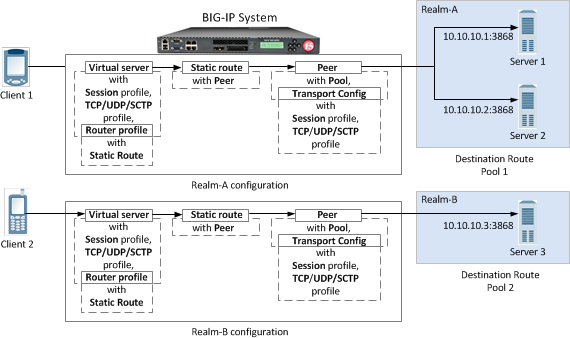
An MRF Diameter routing configuration example
Based on table 2.3.3:
Route entry - ["visa.com", 10000, "", ""] (dia-route-1)
Route entry - ["master.com", 20000, "", ""] (dia-route-2)
A common iRules routing configuration example
ltm pool dr-pool-1 {
    members {
        10.10.20.1:diameter {
            address 10.10.20.1
        }
        10.10.20.2:diameter {
            address 10.10.20.2
        }
    }
}
ltm pool dr-pool-2 {
    members {
        10.10.20.3:diameter {
            address 10.10.20.3
        }
    }
}
An MBLB iRules routing configuration example
ltm virtual diameter-static-route {
    destination 10.10.10.100:3868
    profiles {
       tcp
       diameter
    }
    rules {
        app_routing
    }
}
ltm rule app_routing {
    # Note that this iRule is intended only as an illustration.
    when DIAMETER_INGRESS {
    set newpool ""
    switch [DIAMETER::realm dest] {
            "visa.com" {
                if { [DIAMETER::avp data get "Application-ID"] == 10000 } {
                    set newpool dr-pool-1
                }
            }
            "master.com" {
                if { [DIAMETER::avp data get "Application-ID"] == 20000 } {
                    set newpool dr-pool-2
                }
            }
            default { }
        }
    }
    when LB_SELECTED {
        if { $newpool != "" } {
            LB::reselect pool $newpool
        } else { drop }
    }
    when LB_FAILED { drop }
}
An MRF iRules routing configuration example
ltm virtual diameter-static-route {
    destination 10.10.10.100:3868
    profiles {
       tcp
       dia-profile-1
       dia-router-1
    }
}
ltm message-routing profile diametersession dia-profile-1 { }
ltm message-routing diameter transport transport-1 {
    profiles {
        tcp
        dia-profile-1
    }
}
ltm message-routing diameter peer peer-1 {
    pool dr-pool-1
    transport transport-1
}
ltm message-routing diameter peer peer-2 {
    pool dr-pool-2
    transport transport-1
}
ltm message-routing diameter route dia-route-1 {
    application-id 10000
    destination-realm "visa.com"
    origin-realm ""
    virtual-server ""
    peers { peer-1 }
}
ltm message-routing diameter route dia-route-2 {
    application-id 20000
    destination-realm "master.com"
    origin-realm ""
    virtual-server ""
    peers { peer-2 }
}
ltm message-routing profile diameter-router dia-router-1 {
    routes {
        dia-route-1
        dia-route-2
    }
}


