Applies To:
Show Versions
BIG-IP AAM
- 12.1.5, 12.1.4, 12.1.3, 12.1.2, 12.1.1
BIG-IP APM
- 12.1.6, 12.1.5, 12.1.4, 12.1.3, 12.1.2, 12.1.1
BIG-IP Analytics
- 12.1.6, 12.1.5, 12.1.4, 12.1.3, 12.1.2, 12.1.1
BIG-IP Link Controller
- 12.1.6, 12.1.5, 12.1.4, 12.1.3, 12.1.2, 12.1.1
BIG-IP LTM
- 12.1.6, 12.1.5, 12.1.4, 12.1.3, 12.1.2, 12.1.1
BIG-IP AFM
- 12.1.6, 12.1.5, 12.1.4, 12.1.3, 12.1.2, 12.1.1
BIG-IP PEM
- 12.1.6, 12.1.5, 12.1.4, 12.1.3, 12.1.2, 12.1.1
BIG-IP DNS
- 12.1.6, 12.1.5, 12.1.4, 12.1.3, 12.1.2, 12.1.1
BIG-IP ASM
- 12.1.6, 12.1.5, 12.1.4, 12.1.3, 12.1.2, 12.1.1
Creating an Active-Standby Configuration Using the Setup Utility
Overview: Creating a basic active-standby configuration
This implementation describes how to use the Setup utility to configure two new BIG-IP® devices that function as an active-standby pair. An active-standby pair is a pair of BIG-IP devices configured so that one device is actively processing traffic while the other device remains ready to take over if failover occurs. The two devices synchronize their configuration data and can fail over to one another in the event that one of the devices becomes unavailable.
First, you run the Setup utility on each device to configure base network components (that is, a management port, administrative passwords, and the default VLANs and their associated self IP addresses). Continue running it on each device to establish a trust relationship between the two devices, and create a Sync-Failover type of device group that contains two member devices.
After the Setup utility is run on both devices, each device contains the default traffic group that the BIG-IP system automatically created during setup. A traffic group represents a set of configuration objects (such as floating self IP addresses and virtual IP addresses) that process application traffic. This traffic group actively processes traffic on one of the two devices, making that device the active device. When failover occurs, the traffic group becomes active on (that is, floats to) the peer BIG-IP device.
By default, the traffic group contains the floating self IP addresses of the default VLANs. Whenever you create additional configuration objects such as self IP addresses, virtual IP addresses, and SNATs, the system automatically adds these objects to the default traffic group.
Example
In this configuration example, the device group is named Device Group A. This device group contains two BIG-IP devices, named Device 1 and Device 2, and these two devices are peers of one another. The default traffic group, named traffic-group-1, resides on each device.
Device 1 actively processes traffic because traffic-group-1 is in an Active state on that device. Device 2 remains idle until failover occurs because traffic-group-1 is in a Standby state on that device.
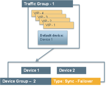
Example active-standby configuration
By implementing this configuration, you ensure that:
- Each device has base network components (such as self IPs and VLANs) configured.
- The two devices can synchronize their configuration to one another.
- Failover capability and connection mirroring are enabled on each device.
Task summary
The configuration process for a BIG-IP® system entails running the Setup utility on each of the two BIG-IP devices. When you run the Setup utility, you perform several tasks. Completing these tasks results in both BIG-IP devices being configured properly for an active-standby implementation.
Licensing and provisioning the BIG-IP system
Configuring a device certificate
- Click Import, import a certificate, click Import, and then click Next.
- Verify the displayed information for the certificate and click Next.
Configuring the management port and administrative user accounts
Enabling ConfigSync and high availability
Configuring the internal network
Configuring the external network
Configuring the network for high availability
Configuring a ConfigSync address
Configuring failover and mirroring addresses
- Locate the Failover Unicast Configuration area of the screen.
-
Under Local Address, confirm that there are entries for the self IP addresses
that are assigned to the HA and
internal VLANs and for the local management IP
address for this device. If these entries are absent, click the
Add button to add the missing entries to the list of
Failover Unicast Addresses.
- For the Address setting, select the address for the VLAN you need to add (either HA or internal).
- In the Port field, type a port number or retain the default port number, 1026.
- Click Repeat to add additional self IP addresses, or click Finished.
- Repeat these steps to add a management IP address.
- Click Next.
- From the Primary Local Mirror Address list, retain the default value, which is the self IP address for VLAN HA.
- From the Secondary Local Mirror Address list, select the address for VLAN internal.
- Click Finished.
Discovering a peer device
You can use the Setup utility to discover a peer device for the purpose of exchanging failover and mirroring information.
Implementation result
To summarize, you now have the following BIG-IP® configuration on each device of the pair:
- A management port, management route, and administrative passwords defined.
- A VLAN named internal, with one static and one floating IP address.
- A VLAN named external, with one static and one floating IP address.
- A VLAN named HA with a static IP address.
- Configuration synchronization, failover, and mirroring enabled.
- Failover methods of serial cable and network (or network-only, for a VIPRION® platform.
- A designation as an authority device, where trust was established with the peer device.
- A Sync-Failover type of device group with two members defined.
- A default traffic group that floats to the peer device to process application traffic when this device becomes unavailable. This traffic group contains two floating self IP addresses for VLANs internal and external.
- One end of an iSession™ connection for WAN traffic optimization.
On either device in the device group, you can create additional configuration objects, such as virtual IP addresses and SNATs. The system automatically adds these objects to Traffic-Group-1.


