Applies To:
Show Versions
BIG-IP LTM
- 15.0.1, 15.0.0, 14.1.2, 14.1.0, 14.0.1, 14.0.0
Overview: Configuring the BIG-IP system as a Layer 2 device with wildcard VLANs
Introduction
To deploy a BIG-IP® system without making changes to other devices on your network, you can configure the system to operate strictly at Layer 2. By deploying a virtual wire configuration, you transparently add the device to the network without having to create self IP addresses or change the configuration of other network devices that the BIG-IP device is connected to.
A virtual wire logically connects two interfaces or trunks, in any combination, to each other, enabling the BIG-IP system to forward traffic from one interface to the other, in either direction. This type of configuration is typically used for security monitoring, where the BIG-IP system inspects ingress packets without modifying them in any way.
Sample configuration
This illustration shows a virtual wire configuration on the BIG-IP system. In this configuration, a VLAN group contains two VLANs tagged with VLAN ID 4096. Each VLAN is associated with a trunk, allowing the VLAN to accept all traffic for forwarding to the other trunk. Directly connected to a Layer 2 or 3 networking device, each interface or trunk of the virtual wire is attached to a wildcard VLAN, which accepts all ingress traffic. On receiving a packet, an interface of a virtual wire trunk forwards the frame to the other trunk and then to another network device.
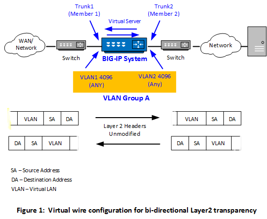
Optionally, you can create a forwarding virtual server that applies a security policy to ingress traffic before forwarding the traffic to the other trunk.
Key points
There are a few key points to remember about virtual wire configurations in general:
- An interface accepts packets in promiscuous mode, which means there is no packet modification.
- The system bridges both tagged and untagged data.
- Source MAC address learning is disabled.
- Forwarding decisions are based on the ingress interface.
- Neither VLANs nor MAC addresses change.
About memory consumption
When you use the BIG-IP Layer 2 Transparency feature, the BIG-IP device switches the traffic at Layer 2, in the absence of any virtual server on the system that matches the traffic. In this case, the device maintains a "connection" state with a default age of 300 seconds. If the number of these connections is large, the BIG-IP device can experience high memory consumption.
To alleviate this, F5 recommends that you take one of the following actions:
- Configure one or more matching virtual servers to handle all traffic.
- If you are unaware of all traffic patterns, configure a wildcard virtual server instead, of type Forwarding (IP) or Performance (Layer 4). This enables the device to perform a connection close operation much more quickly and therefore mitigate high memory consumption.
- Configure a lower threshold for the BigDB variable tm.l2forwardidletimeout.
Create BIG-IP objects for Layer 2 transparency
To configure the BIG-IP system as an inline device operating in Layer 2 transparency mode, you first need to create a virtual wire configuration object. Creating a virtual wire object causes the BIG-IP system to automatically perform these actions:
- Create trunks for accepting all VLAN traffic, with Link Aggregation Protocol (LACP) enabled.
- Set the trunk members (interfaces) to virtual wire mode.
- Create two VLANs with tag 4096 that allow all Layer 2 ingress traffic.
- Create a VLAN group to logically connect the VLANs.
Naming conventions for virtual wire-related objects
For virtual wire-related configuration objects, the BIG-IP system manages object naming in specific ways. See the following table for details.
| Object type | System-named? | Naming convention |
|---|---|---|
| Virtual wire | No | User-defined |
| Trunk | No | User-defined |
| VLAN | Yes | virtual-wire-name_vlan_4096_member_number_xx |
| VLAN group | Yes | Same name as the virtual wire object |
Create a listener for bi-directional traffic
Configuration results
-
Two trunks that represent Member 1 and Member 2 interfaces of the virtual wire. Each interface of a trunk has its forwarding mode set to Virtual Wire .
-
A tagged VLAN for the Member 1 trunk with a tag of 4096, assigning the Member 1 trunk to the VLAN.
-
A tagged VLAN for the Member 2 trunk with a tag of 4096, assigning the Member 2 trunk to the VLAN.
-
A VLAN group with the transparency mode set to Virtual Wire , where the VLAN group name matches the name of the virtual wire object.
-
A virtual server that listens for both client-side and server-side traffic. The virtual server forwards the client-side traffic to the Member 2 trunk and forwards the server-side traffic to the Member 1 trunk.


