Applies To:
Show Versions
BIG-IP AAM
- 14.0.1, 14.0.0
BIG-IP APM
- 14.0.1, 14.0.0
BIG-IP Analytics
- 14.0.1, 14.0.0
BIG-IP Link Controller
- 14.0.1, 14.0.0
BIG-IP LTM
- 14.0.1, 14.0.0
BIG-IP PEM
- 14.0.1, 14.0.0
BIG-IP AFM
- 14.0.1, 14.0.0
BIG-IP DNS
- 14.0.1, 14.0.0
BIG-IP ASM
- 14.0.1, 14.0.0
Message Routing Profiles
Overview: Diameter message routing
The Diameter protocol provides message-routing functionality that the BIG-IP® system supports in a load-balancing configuration.
Diameter message routing configuration
In a message routing configuration, the BIG-IP system manages requests and responses among peers. The following illustration shows a Diameter routing configuration with requests from Client 1 and Client 2 to servers located in different destination realms, Realm-A and Realm-B.
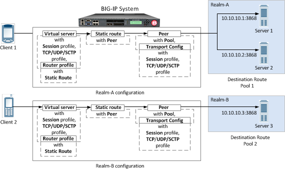
A Diameter message routing configuration
A typical Diameter message routing configuration with two realms involves configuring the following items.
| Functionality | Description |
|---|---|
| Pool | A pool for each realm directs Diameter traffic to servers. |
| Session profile | A session profile for each realm configures a session as a set of messages between two Diameter nodes on behalf of a user. |
| Transport configuration | An optional transport configuration for each realm defines how the BIG-IP system connects with the servers on your network when routing messages. You can assign a transport configuration to a virtual server or peer, as needed. |
| Peer | Each BIG-IP message-routing peer routes messages to a destination host. In this example, BIG-IP message-routing peers route messages to 10.10.10.1:3868, 10.10.10.2:3868, and 10.10.10.3:3868. |
| Static Route | Each static route specifies a set of peers in a destination realm to use in forwarding messages. In this example, Realm-A includes Peer 1 , and Realm-B includes Peer 2. |
| Router profile | A router profile configures Diameter message routing parameters and static routes to be used by a virtual server in routing Diameter messages. |
| Virtual server | Manages Diameter traffic to and from each realm and pool members. |
About the Diameter session profile
The Diameter session profile includes Diameter protocol parameters that can be used by a virtual server or transport configuration in managing Diameter traffic. The profile enables you to configure the properties of a Diameter session as a set of messages between two diameter nodes on behalf of a user. Note that those same two diameter nodes can also include multiple active user sessions. The session profile provides you with parameters to configure settings for timeout, watchdog failures, and message-size, as well as persistence, rewrite, and capabilities-handshake functionality.
| Functionality | Description |
|---|---|
| Settings | Configure timeout functionality, watchdog failures, and message size. |
| Persistence | Configure persistence functionality, including a type, AVP, and timeout. |
| Rewrite | Provide AVP rewriting to conceal clients from servers, as well as to conceal servers from clients. |
| Capabilities Handshake | When the Diameter session profile is configured as a proxy, the BIG-IP system generates capabilities-exchange messages, sending a Capabilities-Exchange-Request (CER) and responding with a Capabilities-Exchange-Answer (CEA), to establish a diameter session with connected nodes. |
You can apply different session profiles to different transport configurations, and then apply the different transport configurations to different message routing peers, which point to different physical pools. You can also apply different session profiles by applying one session profile to the transport configuration, and a different session profile to the virtual server.
About message routing Diameter transport configuration
Message routing Diameter Transport Config functionality defines how the BIG-IP system connects with the servers on your network when routing and load balancing messages. With the transport configuration settings, you can assign a TCP, UDP, or SCTP profile, and Diameter session profile, as well as iRules, a source port, and source address translation.
About message routing peers
A message routing peer defines how the BIG-IP system routes messages to destination hosts. When you configure a message routing peer, you define a pool of destination hosts, and a connection method for them, an optional transport configuration configured with a Diameter session profile, as needed, the number of connections to a destination host, and a ratio value for selection of a peer. After defining the peers, you can use those peers in configuring static routes.
When an inband monitor is assigned to a Diameter message routing pool, the inband monitor marks a pool member down when the total failures from the pool member exceeds or equals the maximum number of failures configured. When a pool member is marked down, the connection remains alive, but load balancing functions only among the remaining pool members within the same pool. The active Diameter monitor marks the pool member up when service is restored.
If a peer does not specify a pool, the BIG-IP system uses the destination IP address and port of the ingress message's connection. If a peer specifies a pool without pool members, the message is unroutable.
When you configure a message routing peer to use a transport configuration, you can enable that peer to use auto-initialization functionality, which automatically creates outbound connections to active pool members in the peer's specified pool. In order for the auto-initialization functionality to work, you need to specify the peer in a static route, and then specify that static route in a router profile that is assigned to a message routing virtual server, The BIG-IP system automatically initiates a connection for each router profile that contains the peer. You enable auto-initialization functionality for a peer by selecting the Auto-Initialization Enabled check box. Additionally, you can specify an Auto-Initialization Interval value, which compensates for latency, to verify the connection between the BIG-IP system and pool members (ranging from 500ms through 65535ms, with a default value of 5000ms). If a connection does not exist, auto-initialization functionality attempts to reestablish a connection.
If a peer does not specify a transport configuration, the BIG-IP system uses the transport type of the message's originating connection.
About Diameter peer selection
When you configure a Diameter static route, the BIG-IP system provides two modes for peer selection: sequential and ratio.
In sequential mode, the BIG-IP system uses peers in the order specified by the Peers Selected list. If a message is retried, the next peer in the Peers Selected list is used.
In ratio mode, the BIG-IP system uses peers in accordance with the peer's ratio value, which you specify when configuring each peer. The relative ratio value for each peer determines whether a peer is selected from the list. For example, a peer with a ratio value of 1 is typically selected over a peer with a ratio value of 2. The lower the ratio value, the greater the probability for selection.
Before configuring a mode for peer selection, you must first configure each peer, using the Peer tab, to include peers in the Available list.
About static routes
The message routing functionality Static Routes enables you to configure a route that specifies a set of peers to use in forwarding messages. When you configure a static route, you can specify an application ID, destination realm, origin realm, virtual server, peer selection mode, and peers.
The required static route attributes (each of which must match the respective request parameter) are prioritized in this order:
- Destination Realm
- Application Id
- Origin Realm
- Virtual Server
A static route is a default route when each of these attributes is set to the default (wildcard) value.
About the Diameter router profile
With the Diameter router profile, you can configure Diameter routing parameters to be used by a virtual server in routing Diameter messages. When you configure a Diameter router profile, you can specify persistence, rewrite, and capabilities-handshake functionality.
About mirroring Diameter message routing
A Diameter proxy and router implementation can mirror client and server connections.
In a high-availability configuration, the active device mirrors connections (including auto-initialization connections) on the standby device, creating and maintaining the same state on each device. The standby device, however, does not route the messages. Instead the standby device stores the messages until the active device notifies the standby device that the message has been routed. This enables the standby device to deliver the message to the equivalent connection for egress processing. A sweeper drops the messages if the standby device stores them longer than the specified value. Enabling this setting ensures a higher level of connection reliability, but it can also affect system performance. As the mirrored messages flow though the client-side connection, normal ingress iRule events and routing occur.
Diameter AVP names
This list specifies supported Diameter Attribute-Value Pair (AVP) names.
AVP Names
- ACCOUNTING-REALTIME-REQUIRED
- ACCOUNTING-RECORD-NUMBER
- ACCOUNTING-RECORD-TYPE
- ACCOUNTING-SUB-SESSION-ID
- ACCT-APPLICATION-ID
- ACCT-INTERIM-INTERVAL
- ACCT-MULTI-SESSION-ID
- ACCT-SESSION-ID
- AUTH-APPLICATION-ID
- AUTH-GRACE-PERIOD
- AUTH-REQUEST-TYPE
- AUTH-SESSION-STATE
- AUTHORIZATION-LIFETIME
- CALLING-STATION-ID
- CLASS
- DESTINATION-HOST
- DESTINATION-REALM
- DISCONNECT-CAUSE
- E2E-SEQUENCE
- ERROR-MESSAGE
- ERROR-REPORTING-HOST
- EVENT-TIMESTAMP
- EXPERIMENTAL-RESULT
- EXPERIMENTAL-RESULT-CODE
- FAILED-AVP
- FIRMWARE-REVISION
- FRAMED-IP-ADDRESS
- HOST-IP-ADDRESS
- INBAND-SECURITY-ID
- MULTI-ROUND-TIME-OUT
- ORIGIN-HOST
- ORIGIN-REALM
- ORIGIN-STATE-ID
- PRODUCT-NAME
- PROXY-HOST
- PROXY-INFO
- PROXY-STATE
- RE-AUTH-REQUEST-TYPE
- REDIRECT-HOST
- REDIRECT-HOST-USAGE
- REDIRECT-MAX-CACHE-TIME
- RESULT-CODE
- ROUTE-RECORD
- SESSION-BINDING
- SESSION-ID
- SESSION-SERVER-FAILOVER
- SESSION-TIMEOUT
- SUBSCRIPTION-ID
- SUBSCRIPTION-ID-DATA
- SUBSCRIPTION-ID-TYPE
- SUPPORTED-VENDOR-ID
- TERMINATION-CAUSE
- USER-EQUIPMENT-INFO
- USER-EQUIPMENT-TYPE
- USER-EQUIPMENT-VALUE
- USER-NAME
- VENDOR-ID
- VENDOR-SPECIFIC-APPLICATION-ID
Overview: Configuring a SIP proxy
You can use the BIG-IP® system as a Session Initiation Protocol (SIP) proxy. When the BIG-IP system is placed between your SIP routers, session border controllers, and soft switches, you can configure the system to route and load balance SIP messages across the servers on your SIP network.
This graphic illustrates the relationships of the configuration objects that you must configure on the BIG-IP system.
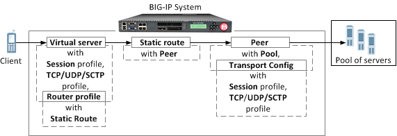
SIP proxy configuration objects
Task summary
About managing MRF SIP session traffic
Through the SIP Session Profile, you can use Message Routing Framework (MRF) to manage SIP traffic across pool members by means of configuring and using Via headers. When you configure Via headers to manage SIP traffic, dependencies between settings apply, enabling you to steer traffic and control requests and responses, as necessary.
Example: SIP session traffic scenario 1 (default)
In SIP session traffic scenario 1 (default), the BIG-IP system receives a request with a Via1 header from a client, and inserts a Via2 header into the request before forwarding the request to the server. When the server provides a response, the BIG-IP system removes the Via2 header from the response, before forwarding the response to the client. If the originating connection no longer exists, the Via2 header that BIG-IP system inserted is no longer available; consequently, the BIG-IP system uses the Via1 header, forwarding the message to the client IP address and port specified by that Via header.
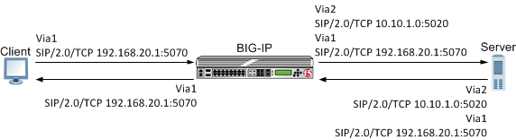
An example of SIP session traffic scenario 1 (default)
When configuring this scenario, the following SIP Session Profile settings apply.
| SIP Session Profile control | Setting or value |
|---|---|
| Honor Via | Enabled |
| Do Not Connect Back | Disabled |
| Insert Via Header | Enabled |
| Custom Via | Not applicable |
Example: SIP session traffic scenario 2
In SIP session traffic scenario 2, the BIG-IP system receives a request with a Via1 header from a client, and inserts a Via2 header into the request before forwarding the request to the server. When the server provides a response, the BIG-IP system removes the Via2 header from the response, before forwarding the response to the client. When the originating connection no longer exists, then the BIG-IP system drops the response message and increments the statistic for Messages failed due to connection dropped.
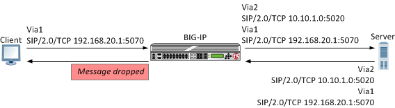
An example of SIP session traffic scenario 2
When configuring this scenario, the following SIP Session Profile settings apply.
| SIP Session Profile control | Setting or value |
|---|---|
| Honor Via | Enabled |
| Do Not Connect Back | Enabled |
| Insert Via Header | Enabled |
| Custom Via | Not applicable |
Example: SIP session traffic scenario 3
In SIP session traffic scenario 3, the BIG-IP system receives a request with a Via1 header from a client, and inserts a Via2 header into the request before forwarding the request to the server. When the server provides a response, the BIG-IP system removes the Via2 header from the response, before forwarding the response to the client. If the originating connection no longer exists, then the Via header that BIG-IP system inserted is no longer available; consequently, the BIG-IP system uses the next available Via header, but, because the Honor Via setting is Disabled, the BIG-IP system does not forward the message to the client IP address and port specified by that Via header.
An example of SIP session traffic scenario 3
When configuring this scenario, the following SIP Session Profile settings apply.
| SIP Session Profile control | Setting or value |
|---|---|
| Honor Via | Disabled |
| Do Not Connect Back | Disabled |
| Insert Via Header | Enabled |
| Custom Via | Not applicable |
Example: SIP session traffic scenario 4
In SIP session traffic scenario 4, the BIG-IP system receives a request with a Via1 header from a client, and inserts a Via2 header into the request before forwarding the request to the server. When the server provides a response, the response from the BIG-IP to the client must be managed by means of an iRule, for example, MR::message nexthop TMM:flow_id or MR::message route virtual vs_name host ip:port.
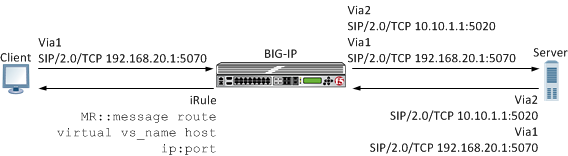
An example of SIP session traffic scenario 4
When configuring this scenario, the following SIP Session Profile settings apply.
| SIP Session Profile control | Setting or value |
|---|---|
| Honor Via | Not applicable |
| Do Not Connect Back | Not applicable |
| Insert Via Header | Enabled |
| Custom Via | Custom Via header value, for example: SIP/2.0/TCP www.siterequest.com:4343 or SIP/2.0/SCTP 10.10.4.32 |
Example: SIP session traffic scenario 5
In SIP session traffic scenario 5, the BIG-IP system receives a request with a Via1 header from a client, but does not insert a Via header into the request before forwarding the request to the server. When the server provides a response, the BIG-IP system uses the client Via1 header in the response to forward the message to the client IP address and port specified by that Via header.
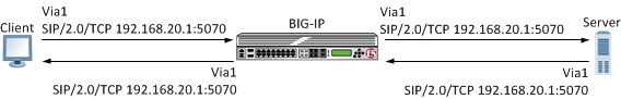
An example of SIP session traffic scenario 5
When configuring this scenario, the following SIP Session Profile settings apply.
| SIP Session Profile control | Setting or value |
|---|---|
| Honor Via | Enabled |
| Do Not Connect Back | Not applicable |
| Insert Via Header | Disabled |
| Custom Via | Not applicable |
Example: SIP session traffic scenario 6
In SIP session traffic scenario 6, the BIG-IP system receives a request with a Via1 header from a client, but does not insert a Via header into the request before forwarding the request to the server. Instead, the BIG-IP system uses the Via1 header specified in the request. When the server provides a response, the BIG-IP system uses the Via1 header in the response, but does not forward the message to the client IP address and port specified by that Via header.
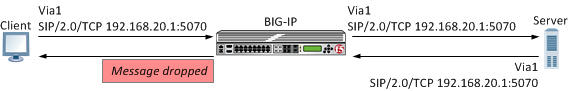
An example of SIP session traffic scenario 6
When configuring this scenario, the following SIP Session Profile settings apply.
| SIP Session Profile control | Setting or value |
|---|---|
| Honor Via | Disabled |
| Do Not Connect Back | Not applicable |
| Insert Via Header | Disabled |
| Custom Via | Not applicable |
Overview: Configuring a SIP message routing firewall
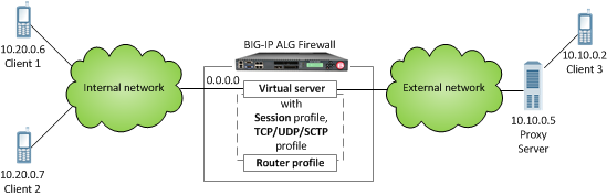
A SIP firewall configuration


