Manual Chapter :
Installing the 4300 Platform
Applies To:
Show Versions
FirePass
- 7.0.0, 6.1.0, 6.0.3
BIG-IP SAM
- 8.0.0
After you have reviewed the hardware requirements and become familiar with the 4300 platform, as described in Working with the 4300 platform, you can install the unit.
There are two types of mounts available to hold the 4300 platform: the standard front rack mount that comes with the 4300 platform, and an optional rail mount that allows you to slide the unit in and out as needed. The tasks you need to perform to install the 4300 platform hardware differ depending on which type of mount you decide to use:
 | Standard front mount If you want to install the 4300 platform into the standard front rack mount that comes with the hardware, you need to install the unit into the rack, and then connect the peripheral hardware and the interfaces. For detailed information, see Installing the 4300 platform hardware, and Connecting the cables and other hardware. |
| | Optional rail mount If you want to install the 4300 platform into a rail mount (using the optional rail-mount kit), you need to perform two preliminary steps. |
| First, you must remove the standard mount-related hardware (known as rack-mount ears) from the unit, because the mount hardware is no longer necessary. |
Once you have completed these tasks, you can then install the unit into the rack and connect the cables and other hardware. For detailed information on installing a rail-mount kit and installing the unit into the rack, see Appendix A, Installing a 4300 Platform Using an Optional Rail-Mount Kit. For information on connecting the cables and other hardware, see Connecting the cables and other hardware.
Whether you are using the standard front mount or the optional rail mount, you should read the following general recommendations before proceeding with the installation of the 4300 platform.
We recommend that all units have 1U spacing between them when mounted in a rack to allow for a rack mounting shelf, and to provide additional air circulation for cooling the unit.
Although not required, a 1U space between units makes it easier for you to remove the unit from the rack in the event that the unit requires service. A 1U space between units also provides additional cable routing options.
We recommend 100 mm spacing from the front panel of the unit to the rack front or rack door. This provides enough room for you to route the cables without bending them excessively.
Warning: This product is sensitive to electrostatic discharge (ESD). We recommend that when you install or maintain the unit, you use proper ESD grounding procedures and equipment.
Warning: Do not turn on a 4300 platform until the management serial console and/or the management network is connected to the unit.
A shelf or similar device is required to support the unit if a single person is installing the unit. To prevent personal injury or damage to the unit, we recommend that at least two people perform the installation.
If you want to use the standard front mount to hold the 4300 platform unit, use the following procedure, To install the unit into a standard-mount rack.
If you are using the optional rail mount kit to hold the unit, use the procedures described in Appendix A, Installing a 4300 Platform Using an Optional Rail-Mount Kit. The appendix describes how to perform the two preliminary tasks of removing the standard mount hardware from the unit and adding the rail hardware to the unit and the rack. The appendix also describes how to install the unit into the rack.
| 2. | Secure the unit using the four rack-mounting screws that are provided. The unit must be securely fastened to the rack to provide adequate stability and to prevent the unit from falling out of the rack. Securing the rack with the screws also provides adequate grounding. |
If the rack you have does not provide adequate support for the unit, you may need a shelf kit. We recommend that you use a shelf kit created by the rack manufacturer. (Some rack manufacturers provide shelf kits for their racks.)
Figure 2.1 shows the orientation of the 4300 platform and the mounting screws for installation in a standard 19" rack. Figure 2.2 shows the 4300 platform installed in the rack.
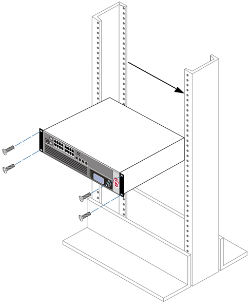
Figure 2.1 Platform orientation for rack mounting
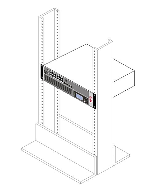
Figure 2.2 Platform installed in a 19" rack
Regardless of which mount type you use to install the unit, you finish the installation by connecting the cables and other hardware. This procedure is described in Connecting the cables and other hardware, following.
After you have installed the unit into the rack, you need to connect certain cables and other hardware. To perform these tasks, use the following procedure. Note that you use this procedure regardless of the type of mount you installed (front mount or rail mount).
| 1. | Connect the hardware that you have chosen to use for input/output. For details about connecting the system to a management workstation or network, see Connecting a Management Workstation or Network, in Installation, Licensing, and Upgrades for BIG-IP® Systems. |
| If you are using a serial terminal as the console, connect the serial cable supplied by F5 Networks to the console port (number 2 in Figure 1.3). |
| If you are using an Ethernet connection, connect a management workstation to the management interface (number 1 in Figure 1.3). |
| 2. | If you have a hardware-based redundant system, connect the failover cable to the failover port on each unit (number 3 in Figure 1.3). |
| 3. | Connect the power cable to the power input panel (number 2 in Figure 1.4), and then connect it to the power source. If the system has the DC power option, a readily accessible disconnect must be incorporated in the wiring for the installation. |
| 4. | Turn on the unit and begin licensing the system. For details about licensing, see Licensing and Configuring the BIG-IP System, in Installation, Licensing, and Upgrades for BIG-IP® Systems. |


