Applies To:
Show Versions
Link Controller
- 4.3 PTF-02, 4.3 PTF-01, 4.3.0
1
Additional Base Network Configuration
- Overview of the base network configuration
- Interfaces
- VLANs
- Self IP addresses
- Trunks
- Spanning Tree Protocol (STP)
- Port mirroring
Overview of the base network configuration
Setting up the base network for the Link Controller means configuring elements such as the Link Controller host name, a default gateway pool, interface media settings, VLANs, and self IP addresses. You perform configuration tasks for the Link Controller base network using the Link Controller Setup utility. For information on using the Setup utility, see Chapter 2, Using the Setup Utility, in the BIG-IP Link Controller Solutions Guide.
Once you have configured the base network elements with the Setup utility, you might want to further enhance the configuration of these elements. This chapter provides the information you need to perform these additional configuration tasks. You can perform these tasks using either the Configuration utility or the bigpipe utility.
Elements you might want to configure further after running the Setup utility are:
- Interfaces
You can set the media type and the duplex mode for an interface, as well as display interface status. - VLANs
VLAN options include tagging and assigning interfaces to VLANs. In addition, you can group separate VLANs together for the purpose of bridging packets between them. - Self IP addresses
You can change self IP addresses or create any number of additional self IP addresses for a VLAN. - Trunks
Trunks are aggregated links. In link aggregation, interfaces can be combined into a trunk to increase bandwidth, in an additive manner. The other benefit of link aggregation is link fail-over. If one link in a trunk goes down, traffic is simply redistributed over the remaining links. - Spanning Tree Protocol (STP)
STP domains provide for loop resolution in configurations where one or more external switches is connected in parallel with a Link Controller. - Port mirroring
This allows you to copy traffic from any interface or set of interfaces on a Link Controller to a single, separate interface. Typically you would install a sniffer device on the target port for debugging and/or monitoring.
Note: Once you have configured the base network, you configure the high-level network for load balancing. Examples of elements you configure as part of the high-level network are: Pools, rules, proxies, and network address translation (SNATs and NATs). For information on how to configure your high-level network, see Chapter 2, Configuring the High-Level Network.
Interfaces
A Link Controller can have as few as two network interfaces and as many as twenty-nine. Before you perform configuration tasks such as displaying interface status and settings, setting the media type, and setting the duplex mode, it is helpful to understand interface naming conventions.
Interface naming conventions
By convention, the Ethernet interfaces on a Link Controller take the name <s>.<p> where s is the slot number of the NIC, and p is the port number on the NIC. For the Application Switch, slot numbering is left-to-right, and port numbering is top-to-bottom, as shown in Figure 1.1 . Note that slot 2 is used for the gigabit ports, and slot 3 is a dedicated administrative port.
When a bigpipe command calls for a list of interfaces, the list may consist of one or more interfaces, with multiple interfaces separated by spaces. For example:
2.1 2.2 2.4 2.6

Figure 1.1 Application Switch slot and port numbering
Displaying status and settings for interfaces
Use the following command to display the current status and the settings for all installed interface cards:
bigpipe interface show
Figure 1.2 is an example of the output you see when you issue this command on an active/standby unit in active mode.
Figure 1.2 The bigpipe interface show command output
interface speed pkts pkts pkts pkts bits bits errors trunk STP


  Mb/s in out drop coll in out


  5.1 UP 100 HD 0 213 0 0 0 74.2K 0


  4.1 UP 100 HD 20 25 0 0 28.6K 33.9K 0
Use the following command to display the current status and the setting for a specific interface.
bigpipe interface <if_name> show
Media type and duplex mode
Properties that are configurable on the interfaces include media type and duplex mode, as shown in Table 1.1 .
Setting the media type
You can set the media type to the specific media type for the interface card or to auto for auto detection. If the media type is set to auto and the card does not support auto detection, the default type for that interface is used, for example 100BaseTX.
Use the following syntax to set the media type:
b interface <if_name> media <media_type> | auto
(The default media type is auto.)
Note: If the Link Controller is inter-operating with an external switch, the media setting should match that of the switch. For more information, see Setting the interface media type, in Chapter 2, Using the Setup Utility, in the BIG-IP Link Controller Solutions Guide.
Setting the duplex mode
You can set the duplex mode to full duplex or half duplex. If the media type does not allow duplex mode to be set, an onscreen message indicates this. If the media type is set to auto, or if setting the duplex mode is not supported for the interface, the duplex setting is not saved to the bigip_base.conf file.
Use the following command to set the duplex mode:
b interface <if_name> duplex full | half | auto
(The default mode is auto.)
VLANs
A VLAN is a grouping of separate networks that allows those networks to behave as if they were a single local area network, whether or not there is a direct ethernet connection between them.
Link Controller offers several options that you can configure for a VLAN. Table 1.2 summarizes the VLAN configuration options.
Default VLAN configuration
The Setup utility automatically configures each interface on the Link Controller as a member of a VLAN. The Link Controller identifies the fastest interfaces, makes the lowest-numbered interface in that group a member of the VLAN external, and makes all remaining interfaces members of the VLAN internal. This creates the default mapping shown in Figure 1.3 .
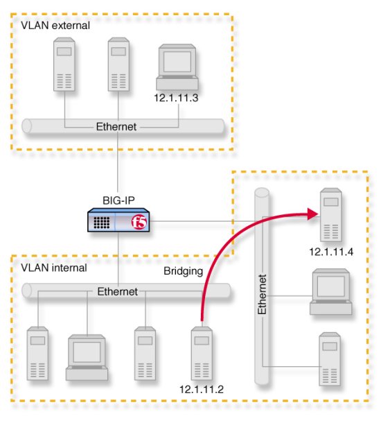
Figure 1.3 Default VLAN configuration
As Figure 1.3 shows, VLAN flexibility is such that separate IP networks can belong to a single VLAN, while a single IP network can be split among multiple VLANs. (The latter case enables you to install the Link Controller into an existing LAN without renaming the nodes.) The VLANs named external and internal are separate networks, and in the configuration shown they behave like separate networks. The networks belonging to the VLAN internal are also separate networks, but have been made to behave like a single network. This is accomplished using a feature called VLAN bridging.
Creating, renaming, and deleting VLANs
Typically, if you use the default configuration, the Setup utility automatically assigns one VLAN to each interface. However, if you need to change your network configuration, or if the default VLANs are not adequate for a network configuration, you can create new VLANs, rename existing VLANs, or delete a VLAN.
To create a VLAN using the Configuration utility
- In the navigation pane, click Network.
The VLANs screen opens. - Click the Add button.
- Type the attributes for the VLAN.
- Click Done.
To rename or delete a VLAN using the Configuration utility
- In the navigation pane, click Network.
The VLANs screen opens. - In the VLANs screen, use one of the following methods:
- To rename a VLAN, click the VLAN name you want to change. The VLAN properties screen opens. Type the new name in the VLAN name box.
- To delete a VLAN, click the Delete button for the VLAN you want to delete.
- Click Done.
To create, rename, or delete a VLAN from the command line
To create a VLAN from the command line, use the following syntax:
b vlan <vlan name> interfaces add <if name> <if name>
For example, if you want to create a VLAN named myvlan that contains the interfaces 1.1 and 1.2, type the following command:
b vlan myvlan interfaces add 1.1 1.2
To rename an existing VLAN, use the following syntax:
b vlan <vlan name> rename <new vlan name>
For example, if you want to rename the VLAN myvlan to yourvlan, type the following command:
b vlan myvlan rename yourvlan
To delete a VLAN, use the following syntax:
b vlan <vlan name> delete
For example, to delete the VLAN named yourvlan, type the following command:
b vlan yourvlan delete
Configuring packet access to VLANs
The Link Controller supports two methods for sending and receiving packets through an interface that is a member of one or more VLANs. These two methods are:
- Port-based access to VLANs - Packets are accepted for a VLAN because the packets have no tags in their headers and were received on an interface that is a member of a VLAN. With this method, an interface is configured as an untagged member of the VLAN. Packets sent out through untagged interfaces contain no tag in their header.
- Tag-based access to VLANs - Packets are accepted for a VLAN because the packets have tags in their headers and the tag matches the VLAN identification number for the VLAN. With this method, an interface is configured as a tagged member of the VLAN. Packets sent out through tagged interfaces contain a tag in their header.
The method used by a VLAN is determined by the way that you add a member interface to a VLAN. When creating a VLAN or modifying VLAN properties (using the Configuration utility or the bigpipe command), you can add an interface to that VLAN as either an untagged or a tagged interface.
The following two sections describe these two methods of providing packet access to a VLAN.
Port-based access to VLANs
Port-based access to VLANs occurs when an interface is added to a VLAN as an untagged interface. In this case, the interface can be added only to that VLAN and to no others. This limits the interface to accepting traffic only from that VLAN, instead of from multiple VLANs. To solve this problem, Link Controller allows you to configure a feature known as tagging, described in the following section.
Tag-based access to VLANs
Tag-based access to VLANs occurs when an interface is added to a VLAN as a tagged interface. A tagged interface can be added to multiple VLANs, thereby allowing the interface to accept traffic from each VLAN of which the interface is a member.
When you add an interface to a VLAN as a tagged interface, the Link Controller associates the interface with the VLAN identification number, or tag, which becomes embedded in the header of a packet.
Note: Every VLAN has a VLAN identification number. This identification number is assigned to a VLAN either explicitly, when a user creates the VLAN, or automatically by the Link Controller, if the user does not supply one.
Each time you add an interface to a VLAN, either when creating a VLAN or modifying its properties, you can designate that interface as a tagged interface. A single interface can therefore have multiple tags associated with it.
The result is that whenever a packet comes into that interface, the interface reads the tag that is embedded in a header of the packet. If the tag in the packet matches any of the tags associated with the interface, the interface accepts the packet. If the tag in the packet does not match any of the tags associated with the interface, the interface rejects the packet.
Example
Figure 1.4 , shows the difference between using three untagged interfaces (where each interface must belong to a separate VLAN) versus one tagged interface (which belongs to multiple VLANs).

Figure 1.4 Equivalent solutions using untagged and tagged interfaces
The configuration on the left shows a Link Controller unit with three internal interfaces, each a separate, untagged interface. This is a typical solution for supporting three separate customer sites. In this scenario, each interface can only accept traffic from its own VLAN.
Conversely, the configuration on the right shows a Link Controller with one internal interface and an external switch. The switch places the internal interface on three separate VLANs. The interface is configured on each VLAN as a tagged interface. In this way, the single interface becomes a tagged member of all three VLANs, and accepts traffic from all three. The configuration on the right is the functional equivalent of the configuration on the left.
Not only can you add a single, tagged interface to multiple VLANs, as shown in the above example, you can also add multiple tagged interfaces to a single VLAN.
Configuration procedures
You configure tag-based access to VLANs using either the Configuration utility or the bigpipe vlan command. You can configure tag-based access either when you create a VLAN and add member interfaces to it, or by modifying the properties of an existing VLAN. In the latter case, you simply change the status of one or more member interfaces from untagged to tagged.
To create a VLAN that supports tag-based access using the Configuration utility
Creating a VLAN that supports tag-based access means creating the VLAN and then adding one or more tagged interfaces to it.
- In the navigation pane, click Network.
The VLAN screen opens. - Click the Add button.
The Add VLAN screen opens. - In the VLAN Name box, type a name for the VLAN.
- In the Tag box, you can specify an optional VLAN ID number. If you do not provide one, Link Controller assigns a default number.
- In the Resources box, specify any tagged interfaces by selecting the appropriate interface numbers from the Interface Number list and clicking tagged >>.
- Configure the other VLAN options.
- Click Done.
To configure tag-based access on an existing VLAN using the Configuration utility
Configuring tag-based access on an existing VLAN means changing the existing status of one or more member interfaces from untagged to tagged.
- In the navigation pane, click Network.
The VLAN screen opens. - Click the VLAN name in the list.
The properties screen for that VLAN opens. - In the Resources box, move any untagged interfaces from the Current Interfaces list to the Interface Number list using the Move button (<<).
- Specify any tagged interfaces by selecting the appropriate interface numbers from the Interface Number list and clicking tagged >>.
- Click Done.
To create a VLAN that supports tag-based access from the command line
- Type the bigpipe vlan command, specifying a VLAN name, the tag keyword, and a VLAN ID number. The following example creates the VLAN external with a VLAN ID of 1209.
b vlan external tag 1209
- Add the interfaces to the VLAN external as tagged interfaces. This is done by specifying the VLAN name, the tagged keyword, and the interfaces to be tagged. For example:
b vlan external interfaces add tagged 4.1 5.1 5.2
The effect of this command is to associate a tag with interfaces 4.1.and 5.1, so that packets with that tag can access the external VLAN.
The above procedure adds multiple tagged interfaces to a single VLAN. However, you can also add a single tagged interface to multiple VLANs (similar to the scenario presented in Figure 1.4, on page 1-8 ). This results in a single interface having more than one tag associated with it. For example, the following commands add the tagged interface 4.1 to the two VLANs external and internal:
b vlan external interfaces add tagged 4.1
b vlan internal interfaces add tagged 4.1
Managing the Layer 2 forwarding table
Layer 2 forwarding is the means by which packets are exchanged directly between nodes on separate VLANs that are members of the same VLAN group, as described in Creating VLAN groups, on page 1-13 . This is accomplished using a simple forwarding table for each VLAN with proxy forward enabled. The forwarding table has an entry for each node in the VLAN and associates the MAC address of that node with the Link Controller interface using the following format:
<MAC address> -> <if>
For example:
00:a0:c9:9e:1e:2f -> 4.1
Viewing and editing the L2 forwarding table
You can view the L2 forwarding table, delete entries, and add static entries. The entries that appear in the table automatically are learned and periodically updated and are called dynamic entries. Entries that you add to the table manually are called static entries. Static entries are not automatically updated. Entering static entries is useful if you have network devices that do not advertise their MAC addresses.
You can view and edit the L2 forwarding table using the bigpipe vlan <vlan_name> fdb command. The <vlan_name> may be either a VLAN or a VLAN group.
To view the L2 forwarding table from the command line
Type the following command:
b vlan <vlan name> fdb show
For example:
b vlan internal fdb show
This produces a display such as the following:
Forwarding table --
00:40:05:30:cc:94 -> 5.1)
To view L2 forwarding table static entries from the command line
Type the following command:
b vlan <vlan name> fdb show static
For example:
b vlan internal fdb show static
To view L2 forwarding table dynamic entries from the command line
Type the following command:
b vlan <vlan name> fdb show dynamic
For example:
b vlan internal fdb show dynamic
To add an entry to the L2 forwarding table from the command line
Type the following command:
b vlan <vlan name> fdb add <MAC address> interface <ifname>
For example:
b vlan internal fdb add <MAC address> interface <ifname>
To delete an entry from the L2 forwarding table from the command line
Type the following command:
b vlan <vlan name> fdb delete <MAC address> interface <ifname>
For example:
b vlan <vlan name> fdb delete 00:a0:c9:9e:1e:2f interface 4.1
vlan <vlan name> fdb show static
vlan <vlan name> fdb show dynamic
vlan <vlan name> fdb show
Setting the L2 forwarding aging time
Entries in the L2 forwarding table have a specified life span, after which they are flushed out if the MAC address is no longer present on the network. This process is called the L2 forward aging time and you can set it using the global variable L2 Aging Time. The default value is 300 seconds.
To set the L2 forwarding aging time using the Configuration utility
- In the navigation pane, click System.
The System Properties screen opens. - Click the Advanced Properties tab.
- In L2 Aging Time box, enter the aging time in seconds.
- Click Done.
To set the L2 forwarding aging time from the command line
Type the following command:
b global l2_aging_time <time_in_seconds>
For example:
b global l2_aging_time 200
Creating VLAN groups
A VLAN group is a grouping of two or more VLANs belonging to the same IP network for the purpose of enabling layer 2 packet forwarding, also known as L2 forwarding, between those VLANs. L2 forwarding is the equivalent of bridging where you want communication between VLANs. By creating a VLAN group, nodes on the separate VLANs can exchange packets directly.
In the example shown in Figure 1.3, on page 1-5 , VLANs external and internal represent separate networks that were originally a single network. You can make them behave like a single network again, much like the networks contained in VLAN internal. You accomplish this by grouping them as shown in Figure 1.5, on page 1-14 .

Figure 1.5 VLANs and a VLAN group
To configure a VLAN group to use layer 2 forwarding, you must:
- Create the VLAN group.
- Assign a self IP address to the VLAN group, for routing purposes.
- Verify that layer 2 forwarding (also known as proxy forwarding) is enabled.
The following sections describe these procedures.
To create a VLAN group
You can create a VLAN group from the command line using the vlangroup command. For example:
b vlangroup network11 vlans add internal external
To assign the self IP address to the VLAN group
You can assign a self IP address to the VLAN group using the following bigpipe command syntax:
b self <ip address> vlan <vlangroup name>
To verify that Layer 2 forwarding is enabled
Layer 2 forwarding is enabled for the VLAN group using the vlan proxy_forward attribute. This attribute is enabled by default when the VLAN group is enabled. To verify that proxy forwarding is enabled, type the following command:
b vlan show
Setting up security for VLANs
You can lock down a VLAN to prevent direct connection to the Link Controller through that VLAN. You can override this lockdown for specific services by enabling the corresponding global variable for that service. For example:
b global open_ssh_port enable
To enable or disable port lockdown using the Configuration utility
- In the navigation pane, click Network.
The VLAN screen opens. - Click the VLAN name in the list.
The properties screen for that VLAN opens. - To enable port lockdown, check the Port Lockdown box.
To disable port lockdown, clear the Port Lockdown check box. - Click Done.
To enable or disable port lockdown from the command line
To enable port lockdown, type:
b vlan <vlan_name> port_lockdown enable
To disable port lockdown, type:
b vlan <vlan_name> port_lockdown disable
Setting fail-safe timeouts for VLANs
For redundant Link Controller pairs, you can enable a failsafe mechanism that will fail over when loss of traffic is detected on a VLAN, and traffic is not restored during the fail-over timeout period for that VLAN. You can enable a fail-safe mechanism to attempt to generate traffic when half the timeout has elapsed. If the attempt is successful, the fail-over is stopped.
To set the fail-over timeout and arm the fail-safe using the Configuration utility
- In the navigation pane, click Network.
The VLAN screen opens. - Click the VLAN name in the list.
The properties screen for that VLAN opens. - Check the Arm Failsafe box and specify the timeout in seconds in the Timeout box.
To set the fail-over timeout and arm the fail-safe from the command line
Using the vlan command, you may set the timeout period and also arm or disarm the fail-safe.
To set the timeout, type:
b vlan <vlan_name> timeout <timeout_in_seconds>
To arm the fail-safe, type:
b vlan <vlan_name> failsafe arm
To disarm the fail-safe, type:
b vlan <vlan_name> failsafe disarm
Setting the MAC masquerade address
You can share the media access control (MAC) masquerade address between Link Controller units in a redundant pair. This has the following advantages:
- Increased reliability and failover speed, especially in lossy networks
- Interoperability with switches that are slow to respond to the network changes
- Interoperability with switches that are configured to ignore network changes
The MAC address for a VLAN is the MAC address of the first interface to be mapped to the VLAN, typically 4.1 for external and 5.1 for internal. You can view the interfaces mapped to a VLAN using the following command:
b vlan show
You can view the MAC addresses for the interfaces on the Link Controller using the following command:
b interface show verbose
Use the following syntax to set the MAC masquerade address that will be shared by both Link Controller units in the redundant system.
b vlan <vlan_name> mac_masq <MAC_addr>
Find the MAC address on both the active and standby units, and pick one that is similar but unique. A safe technique for selecting the shared MAC address follows.
Suppose you want to set up mac_masq on the external interfaces. Using the b interface show command on the active and standby units, you note that their MAC addresses are:
Active: 3.1 = 0:0:0:ac:4c:a2
Standby: 3.1 = 0:0:0:ad:4d:f3
In order to avoid packet collisions, you now must choose a unique MAC address. The safest way to do this is to select one of the addresses and logically OR the first byte with 0x40. This makes the MAC address a locally administered MAC address.
In this example, either 40:0:0:ac:4c:a2 or 40:0:0:ad:4d:f3 would be a suitable shared MAC address to use on both Link Controller units in the redundant system.
The shared MAC address is used only when the Link Controller is in active mode. When the unit is in standby mode, the original MAC address of the network card is used.
If you do not configure mac_masq on startup, or when transitioning from standby mode to active mode, the Link Controller sends gratuitous ARP requests to notify the default router and other machines on the local Ethernet segment that its MAC address has changed. See RFC 826 for more details on ARP.
Note: The MAC masquerade information is stored in the bigip_base.conf file.
Self IP addresses
A self IP address is an IP address mapping to one or more VLANs and their associated interfaces on a Link Controller. You assign a self IP address to each interface on the unit as part of Setup configuration, and you also assign a floating (shared) alias for units in a redundant pair. (A floating self IP address is the address to which the servers behind the Link Controller route traffic). You can create additional self IP addresses for health checking, gateway failsafe, routing, or other purposes. You can create these additional self IP addresses using the self command.
To add a self IP address to a VLAN using the Configuration utility
- In the navigation pane, click Network.
The VLANs screen opens. - Click the Self IP Addresses tab.
- Click the Add button.
- In the IP Address box, type the self IP address to be assigned.
- In the Netmask box, type an optional netmask.
- In the Broadcast box, type an optional broadcast address.
- If you want to configure the self IP address as a floating address, check the Floating box.
- If you want to enable the address for SNAT auto-mapping, check the SNAT Automap box.
- In the VLAN box, type the name of the VLAN to which you want to assign the self IP address.
- Click Done.
To add a self IP address to a VLAN from the command line
Use the following syntax:
b self <addr> vlan <vlan_name> [ netmask <ip_mask> ][ broadcast <broadcast_addr>] [unit <id>]
You can add any number of additional self IP addresses to a VLAN to create aliases. For example:
b self 11.11.11.4 vlan external
b self 11.11.11.5 vlan external
b self 11.11.11.6 vlan external
b self 11.11.11.7 vlan external
Also, any one self IP address may have floating enabled to create a floating alias that is shared by both units of a Link Controller redundant pair:
b self 11.11.11.8 floating enable
Assigning a self IP address to an interface automatically maps it to the VLAN of which it is a member. Assigning a self IP address to an interface not mapped to an untagged VLAN produces an error message.
Enabling or disabling SNAT automap
The self IP addresses you enable on the external VLAN determine the translation address for SNAT auto-mapping. For more information about SNAT auto-mapping, refer to Configuring SNAT automapping, on page 2-69 .
Trunks
Link aggregation is the grouping of links (individual physical interfaces) to form a trunk. Link aggregation increases the bandwidth of the individual links in an additive manner. Thus, four fast Ethernet links, if aggregated, create a single 400 Mbps link. The other advantage of link aggregation is link fail-over. If one link in a trunk goes down, traffic is simply redistributed over the remaining links.
A trunk must have a controlling link, and acquires all the attributes of that controlling link from layer 2 and above. The trunk automatically acquires the VLAN membership of the controlling link but does not acquire its media type and speed. Outbound packets to the controlling link are load balanced across all of the known-good links in the trunk. Inbound packets from any link in the trunk are treated as if they came from the controlling link.
A maximum of eight links may be aggregated. For optimal performance, links should be aggregated in powers of two. Thus, you ideally will aggregate two, four, or eight links.
To configure a trunk using the Configuration utility
- In the navigation pane, click Network.
The Network screen opens. - Click the Trunks tab.
The Trunks screen opens. - Click the Add button.
- Select the link that is to be the controlling link from the Available Interfaces list, and click controlling >>.
The interface appears at the top of the Aggregated Interfaces list. - Select the remaining link(s) from the Available Interfaces list and click aggregated >>.
The interface(s) appears in the Aggregated Interfaces list below the controlling link. - Click Done.
To configure a trunk from the command line
Use the following syntax to configure a trunk from the command line:
b trunk <controlling_if> define <if_list>
Interfaces are specified using the s.p convention, where s is slot number and p is port number. An <if_list> is one or more such interfaces, with multiple interfaces separated by spaces.
For more information on interface naming, refer to Interface naming conventions, on page 1-2 .
Spanning Tree Protocol (STP)
The Link Controller provides Spanning Tree Protocol (STP) implementation for loop resolution in configurations where one or more external switch is connected in parallel with the Link Controller. You can use this feature to configure two or more interfaces on the unit as an STP domain. For interfaces in the STP domain, the spanning tree algorithm identifies the most efficient path between the network segments, and establishes the switch associated with that path as the root. Links forming redundant paths are shut down, to be re-activated only if the root fails.
The STP domain should contain all ports that are connected in parallel to an external switch where there are nodes on the link capable of generating or receiving traffic. A second domain is called for if there is an additional switch or switches connected in parallel with additional Link Controller interfaces.
Warning: Use of STP may slow performance significantly, particularly if more than one STP domain is created, and may have unforeseen effects on complex networks. It is important to test your STP configuration before placing it online.
Creating and deleting STP domains
You can create or delete STP domains using the Configuration utility or from the command line.
To create an STP domain using the Configuration utility
- In the navigation pane, click Network.
The Network screen opens. - Click the STP tab.
The Trunks screen opens. - Click the Add button.
- Configure the STP domain attributes.
- Click Done.
To create or delete an STP domain from the command line
To create an STP domain from the command line, use the following syntax:
b stp <stp_name> interfaces add <if _list> | all
For example, if you want to create an STP domain named mystp that contains the interfaces 1.1 and 1.2, type the following command.
b stp mystp interfaces add 1.1 1.2
If you want to create an STP domain named mystp that contains all interfaces on the Link Controller, type:
b stp <stp_name> interfaces add all
To delete an STP domain, use the following syntax:
b stp <stp_name> delete
Setting time intervals for an STP domain
You can set the time intervals in seconds for hello, max_age, and forward_delay for the STP domain from the command line using the following syntax:
b stp <stp_name> hello <interval>
b stp <stp_name> max_age <interval>
b stp <stp_name> forward_delay <interval>
Adding or deleting interfaces in an STP domain
To add interfaces to an STP domain from the command line, use the following syntax:
b stp <stp_name> interfaces add <if _list>
To delete interfaces from an STP domain, use the following syntax.
b stp <stp_name> interfaces delete <if _list>
Disabling and re-enabling an STP domain
To disable an STP domain from the command line, use the following syntax:
b stp <stp_name> disable
To re-enable interfaces on an STP domain, use the following syntax:
b stp <stp_name> enable
Note: Disabling or deleting all interfaces on an STP domain disables the domain. You cannot re-enable the domain without adding interfaces.
Disabling and re-enabling interfaces in an STP domain
To disable specific interfaces in the STP domain from the command line, use the following syntax:
b stp <stp_name> interfaces disable <if_list>
To re-enable interfaces in an STP domain, use the following syntax:
b stp <stp_name> interfaces enable <if_list>
Restarting stpd
The stpd does not automatically restart when you synchronize configurations between units in a Link Controller redundant pair. In order to restart the stpd, type the following command:
bigstart restart stpd
Port mirroring
For the IP Application Switch, you can copy traffic from any port or set of ports to a single, separate port. This is called port mirroring. You should attach a sniffer device to the target port (called the mirror-to port) for debugging and/or monitoring.
Setting up a port mirror
Port mirroring consists of specifying a mirror-to port and adding to it one or more ports (that is, a port list) to be mirrored. You can set up port mirroring using the Configuration utility or from the command line.
To set up port mirroring using the Configuration utility
- In the navigation pane, click Network.
The Network screen opens. - Click the Interfaces tab.
- Click the Port Mirroring subtab.
- In the Port Mirroring screen, configure the port mirror attributes.
- Click Done.
To set up port mirroring from the command line
Use this bigpipe syntax for setting up port mirroring:
b mirror <mirror_to_if> interfaces add <if_list>
Example:
b mirror 3.24 interfaces add 3.1 3.3 3.10
Deleting interfaces from a port mirror or deleting a port mirror
You can delete individual interfaces from a port mirror, or you can completely delete a port mirror.
To delete interfaces from the port mirror using the command line
Use this bigpipe syntax to delete interfaces from the port mirror:
b mirror <mirror_to_if> interfaces delete <if_list>
For example:
b mirror 3.24 interfaces delete 3.10
To delete the port mirror from the command line
Use this bigpipe syntax to delete the port mirror:
b mirror <mirror_to_if> delete
For example:
b mirror 3.24 delete


