Manual Chapter : Configuring the Link Controller System to Manage Traffic

Applies To:

Show Versions Show Versions

BIG-IP Link Controller

  • 13.1.5, 13.1.4, 13.1.3, 13.1.1, 13.1.0, 13.0.1, 13.0.0, 12.1.6, 12.1.5, 12.1.4, 12.1.3, 12.1.2, 12.1.1, 12.1.0
Manual Chapter

Configuring the Link Controller System to Manage Traffic

Overview: Configuring the Link Controller system to manage traffic

Important: This functionality is not currently available in the U.S.

The BIG-IP® Link Controller™ provides a variety of methods for managing the traffic flowing in and out of a network. In order to integrate Link Controller into your network to manage traffic, you must complete a specific set of tasks for the capabilities of Link Controller to be available to you.

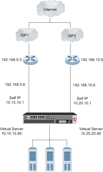
The following illustration shows a network for configuring the Link Controller system to manage Internet traffic on two connections using two different Internet service providers (ISPs).

Example of a network for configuring a Link Controller system to manage traffic

About the initial setup of Link Controller

Before you configure Link Controller™ on a BIG-IP® device, make sure you complete the following:

  • Install the BIG-IP hardware with an initial network configuration applied.
  • Provision Link Controller at the level Nominal or Dedicated.
  • Configure the management IP address, network mask, and management route on the BIG-IP system.
  • Designate the host name of the system as a fully qualified domain name (FQDN).
  • Define the user name and password on the system that you will use when logging in to the BIG-IP Configuration utility.
  • License the appropriate BIG-IP software.

Task summary

Important: This functionality is not currently available in the U.S.

Use the tasks in this implementation to integrate BIG-IP® Link Controller™ into your network. After completed, you can configure a variety of methods for managing the traffic flowing in and out of a network, including cost-based and bandwidth load balancing.

Task list

Creating VLANs for communication between the network and links

Before you begin creating VLANs, ensure that you have completed the initial setup of the Link Controller™ system.
Create VLANs to encompass the IP addresses associated with Link Controller and the other network components that help manage DNS traffic.
  1. On the Main tab, click Network > VLANs .
    The VLAN List screen opens.
  2. Click Create.
    The New VLAN screen opens.
  3. In the Name field, type the name of the first VLAN.
  4. In the Tag field, type a numeric tag, between 1-4094, for the VLAN, or leave the field blank if you want the BIG-IP system to automatically assign a VLAN tag.
    The VLAN tag identifies the traffic from hosts in the associated VLAN.
  5. If you want to use Q-in-Q (double) tagging, use the Customer Tag setting to perform the following two steps. If you do not see the Customer Tag setting, your hardware platform does not support Q-in-Q tagging and you can skip this step.
    1. From the Customer Tag list, select Specify.
    2. Type a numeric tag, from 1-4094, for the VLAN.
    The customer tag specifies the inner tag of any frame passing through the VLAN.
  6. For the Interfaces setting:
    1. From the Interface list, select an interface number.
    2. From the Tagging list, select Tagged or Untagged.
      Select Tagged when you want traffic for that interface to be tagged with a VLAN ID.
    3. If you specified a numeric value for the Customer Tag setting and from the Tagging list you selected Tagged, then from the Tag Mode list, select a value.
    4. Click Add.
  7. Click Finished.
  8. Repeat these steps to create two additional VLANs.

Creating a default gateway pool

Gather the IP addresses associated with each link.
Create a default gateway pool to load balance the outbound traffic across the links.
  1. On the Main tab, click Local Traffic > Pools .
    The Pools list screen opens.
  2. Click Create.
  3. In the Name field, type a name for the pool.
    Names must begin with a letter, and can contain only letters, numbers, and the underscore (_) character.
    Important: The pool name is limited to 63 characters.
  4. In the New Members area, add the IP addresses associated with each link.
    1. In the Address field, type the IP address.
    2. Click Add.
  5. Click Finished.

Creating a default route to the Internet

Configure Link Controller™ to use the pool as the default gateway connection between the internal network and the Internet.
  1. On the Main tab, click Network > Routes .
  2. Click Add.
    The New Route screen opens.
  3. In the Name field, type a unique name.
  4. From the Resource list, select Use Pool.
  5. From the Pool list, select default_gateway_pool.
  6. Click Finished.

Creating links to define the physical connections to the Internet

Gather the IP addresses of the routers associated with the ISPs and IP addresses, which correspond with the external Internet connections.
Create links using the IP addresses of routers on the network that provide a path to the Internet.
  1. On the Main tab, click Link Controller > Links .
    The Links List screen opens.
  2. Click Create.
  3. In the Name field, type a name for the link that represents one of the ISPs.
  4. In the Router Address field, type the IP address of the router associated with the ISP.
  5. In the Uplink Address field, type the IP address that corresponds with the external Internet connection.
  6. In the Service Provider field, type the name of the ISP.
  7. For the Health Monitors setting, from the Available list, select bigip_link and gateway_icmp and move the monitors to the Enabled list.
  8. Click Create.
  9. Repeat these steps to create the second service provider link.

Creating listeners to detect traffic coming from ISPs

Gather the self IP addresses on which Link Controller™ listens for traffic.
Create two listeners for detecting DNS traffic.
  1. On the Main tab, click Link Controller > Listeners .
    The Listeners List screen opens.
  2. Click Create.
    The Listeners properties screen opens.
  3. In the Destination field, type the self IP address on which the Link Controller listens for traffic.
  4. From the Protocol drop-down list, select either UDP or TCP.
    Note: The listener uses the UDP or TCP protocol to listen for connections on the enabled VLANs. The default is UDP. Zone transfers require the TCP protocol.
  5. Click Finished.
  6. Repeat these steps to create the second listener.

Creating a load balancing pool

Create a load balancing pool to process the inbound traffic from the Internet.
  1. On the Main tab, click Local Traffic > Pools .
    The Pool List screen opens.
  2. Click Create.
    The New Pool screen opens.
  3. In the Name field, type a unique name for the pool.
    Names must begin with a letter, and can contain only letters, numbers, and the underscore (_) character.
    Important: The pool name is limited to 63 characters.
  4. For the Health Monitors setting, from the Available list, select the http monitor and move the monitor to the Active list.
  5. Click Finished.

Creating virtual servers to load balance connections across servers

Gather the IP addresses you want to use for creating the virtual servers.
Create two virtual servers, one for each link, to load balance inbound connections across the servers on the network.
  1. On the Main tab, click Local Traffic > Virtual Servers .
    The Virtual Server List screen opens.
  2. Click the Create button.
    The New Virtual Server screen opens.
  3. In the Name field, type a unique name for the virtual server.
  4. In the Destination Address field, type the IP address you want to use for the virtual server.
  5. In the Service Port field, type 80, or select HTTP from the list.
  6. Click Finished.
  7. Repeat these steps to create the second virtual server.

Creating a wildcard virtual server

Create a wildcard server to load balance outbound connections across the routers.
  1. On the Main tab, click Local Traffic > Virtual Servers .
    The Virtual Server List screen opens.
  2. Click the Create button.
    The New Virtual Server screen opens.
  3. In the Name field, type a unique name for the virtual server.
  4. For the Destination setting, select Network, and type 0.0.0.0 in the Address field and 0.0.0.0 in the Mask field.
  5. In the Service Port field, type 0.
    Note: Port 0 defines a wildcard virtual server that handles all types of services. If you specify a port number, you create a port-specific wildcard virtual server. In that case, the wildcard virtual server handles traffic only for the specified port.
  6. In the Resources area, from the Default Pool list, select default_gateway_pool.
  7. Click Finished.

Creating a wide IP that encompasses virtual servers

Gather the IP addresses of the two virtual servers that you created previously.
Create a wide IP that encompasses the virtual servers.
  1. On the Main tab, click Link Controller > Inbound Wide IPs .
    The Wide IP List screen opens.
  2. Click Create.
    The New Wide IP screen opens.
  3. In the Name field, type a name for the wide IP.
  4. From the Type list, select a record type for the wide IP.
  5. From the Load Balancing Method list, make selections from the Preferred, Alternate, and Fallback lists.
  6. For the Member List field, add the virtual servers that you created previously.
    1. From the Virtual Server list, select a virtual server.
    2. Click Add.
  7. Click Finished.

Implementation result

Now Link Controller™ is configured to manage the DNS traffic in and out of a network.