Applies To:
Show Versions
BIG-IQ ADC
- 4.5.0
BIG-IQ Cloud
- 4.5.0, 4.4.0, 4.3.0
BIG-IQ Device
- 4.5.0, 4.4.0, 4.3.0
BIG-IQ Security
- 4.5.0, 4.4.0, 4.3.0
BIG-IQ Centralized Management
- 5.4.0, 5.3.0, 5.2.0, 5.1.0, 5.0.0, 4.6.0
Platform Installation
About installing the platform
After you have reviewed the hardware requirements and become familiar with the BIG-IQ® 7000 Series platform, you can install the unit.
About general recommendations for rack mounting
Although not required, a 1U space between units makes it easier for you to remove the unit from the rack in the event that the unit requires service. A 1U space between units also provides additional cable routing options.
Leaving at least 100 mm of space from the front panel of the unit to the rack front or rack door provides enough room for you to route the cables without excessive bending or insulation damage.
A shelf or similar device is required to support the unit if only one person is installing the unit.
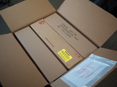
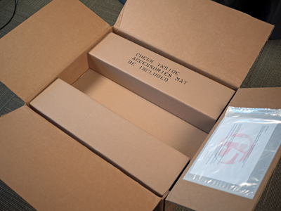
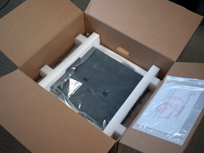
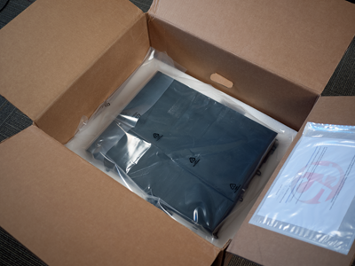
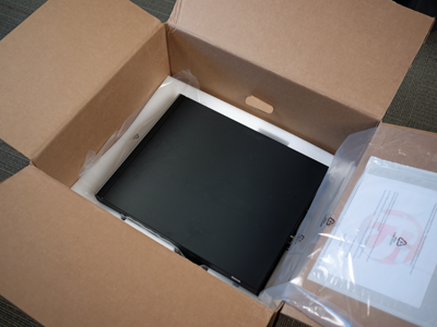
Unpacking the platform
-
If you have not already done so, open the top of the shipping box.
-
Remove the mounting options box from the accessory tray.
-
Remove the accessory tray from the shipping box.
The accessory tray includes compartments that contain the bezel box, and accessory boxes for the AC power cords or DC connectors, cables, and optical transceivers.
-
Remove the upper foam inserts.
-
Remove the plastic wrapping sheeting from the platform, and then
remove the platform from the shipping box.
Determining which rack mounting kit to use
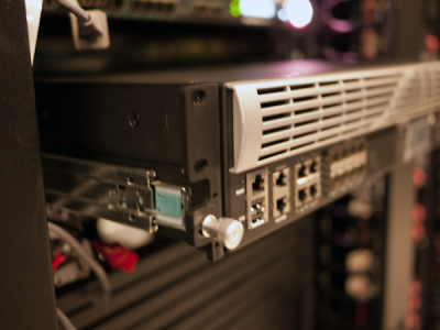
The BIG-IQ® 7000 Series platform comes with two types of rack mounting kits: sliding quick-install rail-mounting and stationary front-mounting. An advantage of installing the quick-install kit is that you can then slide the unit in and out of the rack as needed.
The tasks required to install the platform might differ depending on the type of rack mount you decide to use or which type of cabinet unit you are installing into (single two-post cabinet or four-post cabinet).
About the front-mount/rail lock brackets
You must use the front-mount/rail lock brackets (left and right) if you are installing into either a two-post or four-post rack and in two installation configurations:
- Stationary front-mounting
- Sliding quick-install rail-mounting
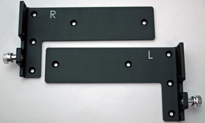
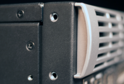
The front-mount brackets
About the quick-install rail kit
Use the quick-install rail kit if you want to be able to slide the unit in or out of the rack for maintenance activities. The kit includes two rails (left and right) and eight #8-32 thumb screws. The rails snap into place in the rack, and no tools are required to install a platform using this kit.
The rails are optimized for installation into square hole cabinets, but they can be installed in other cabinet styles, such as round hole cabinets, using the screws provided. The rails are easily converted to mount to either cabinet style.
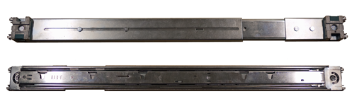
Quick-install rail kit
For information about installing the platform using the quick-install rail kit, see the instruction guide provided by the manufacturer, which is included with the kit hardware.
After installing the platform, secure it to the rack with the rail lock brackets that are provided. Attach the front bezel to the unit by grasping the bezel using the indentations located on either side and applying a gentle forward, slightly upward force to the left side. This helps ensure that the left side is mounted flush to the unit .
Installing using the front-mount/rail lock brackets
This platform includes front-mount/rail lock brackets, which you can use to either attach the unit directly to the rack or secure a rail-kit mounted unit to the rack.
The rail lock thumb screw is integrated with the front-mount/rail lock bracket. Use the thumb screw to secure the unit to the rack when using the quick-install rail kit.
-
Mount the bracket to the unit using the M4 flat head countersink
screws (five per side).
The screws must be torqued to 16-18 inch-pounds.Note: The brackets are marked with L for left side and R for right side.
-
If you are installing the unit into the rack using the quick-install
rail kit:
-
Use the captive screw that is attached to the bracket to
secure the brackets to the rack on each side of the unit.
Use 18 to 20 inch-pounds (2.0 to 2.3 Newton-meters) of torque on these screws.
-
Use the captive screw that is attached to the bracket to
secure the brackets to the rack on each side of the unit.
-
Attach the front bezel to the unit by grasping the bezel on either
side using the indentations provided and applying a gentle forward,
slightly upward force to the left side. This helps ensure that the
left side is mounted flush to the unit.
Note: Failure to use the indentations could result in pinched fingers.
About grounding the platform
You should ground the platform after you install it in a rack. The chassis ground lug is located on the back of the platform.
Do not secure multiple bonding or grounding connectors with the same bolt. The grounding connectors do not need to be removed to perform service or installation procedures. You can connect other bonding or grounding conductors to a grounding connector provided a reliable bond between the connector and the equipment is not disturbed during installation, service, or maintenance of the platform.
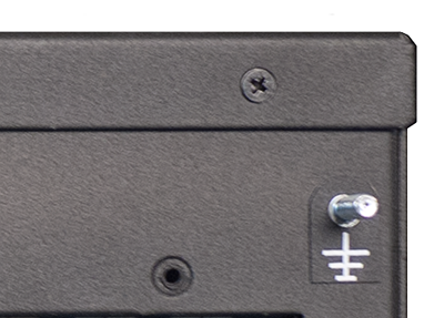
Chassis ground lug
Connecting the ground lug to the ground terminal
Connecting the cables and other hardware
-
Connect to a serial console server. Depending on which BIG-IP® system you have, you can use either the
supplied RJ45 to DB9 console port cable or the RJ45F to RJ45M rolled
serial adapter to connect the BIG-IP system to a serial console.
- Connect the RJ45 to DB9 console port cable to the
CONSOLE port on the BIG-IP system.
Note: The default baud rate is 19200,n,8,1.
- Connect the RJ45F to RJ45M rolled serial adapter to the
console port if you are connecting the system to a serial console
server with a standard CAT5 cable, and then connect the CAT5 cable
to the adapter. The adapter provides the appropriate pinout
connection to your equipment.
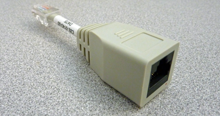
The RJ45F to RJ45M rolled serial (pass-through) adapter
- Connect the RJ45 to DB9 console port cable to the
CONSOLE port on the BIG-IP system.
You can now assign a management IP address to the system, and then license and provision the software.
Optionally, you should run the latest version of the qkview utility. This utility collects configuration and diagnostic information about your system into a single file that you can provide to F5 Technical Support to aid in troubleshooting. For more information, see http://support.f5.com/kb/en-us/solutions/public/12000/800/sol12878.html.
Configuring a management IP address using the LCD panel
- Press the X button to activate Menu mode for the LCD.
- Press the Check button to select System.
-
To configure the management IP address using DHCP:
- Press the Check button to select DHCP.
- Press the Check button to select enabled.
-
To configure the management IP address manually:
- Press the Check button to select Management.
- Press the Check button to select Address Type, and then press the Check button again to select either IPv4 or IPv6.
- Use the arrow keys to select Mgmt IP and press the Check button.
- Use the arrow keys to configure the management IP address.
- Use the arrow keys to select Prefix Length and press the Check button.
- Use the arrow keys to configure the length of the routing prefix for the IPv4 or IPv6 management IP address.
- Use the arrow keys to select Mgmt Gateway and press the Check button.
- Use the arrow keys to configure the default route for the management interface.
- Use the arrow keys to select Commit and press the Check button.


