Applies To:
Show Versions
BIG-IP LTM
- 11.5.10, 11.5.9, 11.5.8, 11.5.7, 11.5.6, 11.5.5, 11.5.4, 11.5.3, 11.5.2, 11.5.1
Other Application-Layer Profiles
Overview of other application-layer profiles
BIG-IP® Local Traffic Manager™offers several features that you can use to intelligently control your application layer traffic. These features are available through various configuration profiles.
A profile is a group of settings, with values, that correspond to a specific type of traffic, such as FTP traffic. A profile defines the way that you want the BIG-IP system to manage that traffic type. After you configure the type of profile you need, you assign it to a virtual server.
To manage application layer traffic, you can use any of these profile types:
- FTP (File Transfer Protocol)
- DNS (Domain Name System)
- RTSP (Real Time Streaming Protocol)
- ICAP (Internet Content Adaptation Protocol)
- Request Adapt and Response Adapt
- Diameter
- RADIUS (Remote Authentication Dial-In User Service)
- SIP (Session Initiation Protocol)
- SMTP
- SMTPS
- iSession
- Rewrite
- XML
- SPDY
- FIX
- video Quality of Experience (QOE)
In addition to these application layer profiles, Local Traffic Manager includes other features to help you manage your application traffic, such as health monitors for checking the health of an FTP service, and iRules® for querying or manipulating header or content data. Additional profiles may be available with other modules.
About HTTP compression profiles
HTTP compression reduces the amount of data to be transmitted, thereby significantly reducing bandwidth usage. All of the tasks needed to configure HTTP compression on the BIG-IP® system, as well as the compression software itself, are centralized on the BIG-IP system. The tasks needed to configure HTTP compression for objects in an Application Acceleration Manager module policy node are available in the Application Acceleration Manager, but an HTTP compression profile must be enabled for them to function.
When configuring the BIG-IP system to compress data, you can:
- Configure the system to include or exclude certain types of data.
- Specify the levels of compression quality and speed that you want.
You can enable the HTTP compression option by setting the URI Compression or the Content Compression setting of the HTTP Compression profile to URI List or Content List, respectively. This causes the BIG-IP system to compress HTTP content for any responses in which the values that you specify in the URI List or Content List settings of an HTTP profile match the values of the Request-URI or Content-Type response headers.
Exclusion is useful because some URI or file types might already be compressed. Using CPU resources to compress already-compressed data is not recommended because the cost of compressing the data usually outweighs the benefits. Examples of regular expressions that you might want to specify for exclusion are .*\.pdf, .*\.gif, or .*\.html.
HTTP Compression profile options
You can use an HTTP Compression profile alone, or with the BIG-IP® Application Acceleration Manager, to reduce the amount of data to be transmitted, thereby significantly reducing bandwidth usage. The tasks needed to configure HTTP compression for objects in an Application Acceleration Manager policy node are available in the Application Acceleration Manager, but an HTTP Compression profile must be enabled for them to function.
About Web Acceleration profiles
When used by BIG-IP® Local Traffic Manager™ without other provisioned modules, the Web Acceleration profile uses basic default acceleration.
Web Acceleration profile settings
This table describes the Web Acceleration profile configuration settings and default values.
| Setting | Value | Description |
|---|---|---|
| Name | No default | Specifies the name of the profile. |
| Parent Profile | Selected predefined or user-defined profile | Specifies the selected predefined or user-defined profile. |
| Partition / Path | Common | Specifies the partition and path to the folder for the profile objects. |
| Cache Size | 100 |
This setting specifies the maximum size in megabytes (MB) reserved for the cache. When the cache reaches the maximum size, the system starts removing the oldest entries. |
| Maximum Entries | 10000 | Specifies the maximum number of entries that can be in the cache. |
| Maximum Age | 3600 | Specifies how long in seconds that the system considers the cached content to be valid. |
| Minimum Object Size | 500 | Specifies the smallest object in bytes that the system considers eligible for caching. |
| Maximum Object Size | 50000 | Specifies the largest object in bytes that the system considers eligible for caching. |
| URI Caching | Not Configured | Specifies whether the system retains or excludes certain Uniform Resource Identifiers (URIs) in the cache. The process forces the system either to cache URIs that typically are ineligible for caching, or to not cache URIs that typically are eligible for caching. |
| URI List | No default value | Specifies the URIs that the system either includes in or excludes from caching.
|
| Ignore Headers | All | Specifies how the system processes client-side
Cache-Control headers when caching is enabled.
|
| Insert Age Header | Enabled | Specifies, when enabled, that the system inserts Date and Age headers in the cached entry. The Date header contains the current date and time on the BIG-IP® system. The Age header contains the length of time that the content has been in the cache. |
| Aging Rate | 9 | Specifies how quickly the system ages a cache entry. The aging rate ranges from 0 (slowest aging) to 10 (fastest aging). |
| AM Applications | No default | Lists enabled Application Acceleration Manager applications in the Enabled field and available applications in the Available field. |
Web Acceleration Profile statistics description
This topic provides a description of Web Acceleration Profile statistics produced in tmsh.
Viewing Web Acceleration profile statistics
Statistics for the Web Acceleration Profile can be viewed in tmsh by using the following command.
tmsh show /ltm profile web-acceleration <profile_name>
Each statistic is described in the following example, appended after the asterisk (*).
---------------------------------------------
Ltm::Web Acceleration Profile: wa-profile-rbk
---------------------------------------------
Virtual Server Name               N/A

Cache
  Cache Size (in Bytes)             *current cache size for this profile
  Total Cached Items                *items in local cache
  Total Evicted Items               *count of items that have been evicted
                                     from the local cache
  Inter-Stripe Size (in Bytes)      *all the remote tmms cache
  Inter-Stripe Cached Items         *remote tmms count of cached items
  Inter-Stripe Evicted Items        *remote tmms count of cached items
                                     that have been evicted

Cache Hits/Misses               Count  Bytes
  Hits                              0      0  *tmm local cache served
                                               response
  Misses (Cacheable)                0      0  *tmm local cache items that
                                               match a rule set but are
                                               not in cache
  Misses (Total)                    0      0  *tmm local cache items that
                                               either match or do not match
                                               rule set and are not served
                                               from cache
  Inter-Stripe Hits                 0      0  *successful local access of
                                               remote caches
  Inter-Stripe Misses               0      -  *unsuccessful local access
                                               of remote caches
  Remote Hits                       0      0  *successful remote tmms
                                               accessing local cache
  Remote Misses                     0      -  *unsuccessful remote tmms
                                               accessing local cache
|
FTP profiles
Local Traffic Manager™ includes a profile type that you can use to manage File Transfer Protocol (FTP) traffic. You can tailor FTP profile settings to your specific needs. For those settings that have default values, you can retain those default settings or modify them. You can modify any settings either when you create the profile, or at any time after you have created it.
The Translate Extended value
Because IP version 6 addresses are not limited to 32 bits (unlike IP version 4 addresses), compatibility issues can arise when using FTP in mixed IP-version configurations.
By default, Local Traffic Manager automatically translates FTP commands when a client-server configuration contains both IP version 4 (IPv4) and IP version 6 (IPv6) systems. For example, if a client system running IPv4 sends the FTP PASV command to a server running IPv6, Local Traffic Manager automatically translates the PASV command to the equivalent FTP command for IPv6 systems, EPSV.
Local Traffic Manager translates the FTP commands EPRV and PORT in the same way.
Inherit Parent Profile
When you configure the BIG-IP® system to process FTP traffic, the FTP virtual server fully proxies the control channel, allowing you to use the optimization settings of the client-side and server-side TCP profiles assigned to the virtual server.
However, the profile settings of the FTP control channel are not passed down to the FTP data channel by default. Instead, the FTP data channel uses a Fast L4 flow, which is fully accelerated by Packet Velocity ASIC to maximize performance (on applicable hardware platforms). A data channel using Fast L4 cannot use the same full-proxy TCP optimizations that exist for the control channel.
To take advantage of these optimizations for the FTP data channel, you can enable the Inherit Parent Profile setting of the FTP profile. Enabling this setting disables Fast L4 for the FTP data channel, and instead allows the data channel to use the same TCP profile settings that the control channel uses.
Data Port
The Data Port setting allows the FTP service to run on an alternate port. The default data port is 20.
Security for FTP traffic
When the BIG-IP system includes a license for the BIG-IP® Application Security Manager™, you can enable a security scan for FTP traffic.
DNS profiles
You can create a custom DNS profile to enable various features such as converting IPv6-formatted addresses to IPv4 format, enabling DNS Express™, and enabling DNSSEC.
RTSP profiles
Local Traffic Manager® includes a profile type that you can use to manage Real Time Streaming Protocol (RTSP) traffic. Real Time Streaming Protocol (RTSP) is a protocol used for streaming-media presentations. Using RTSP, a client system can control a remote streaming-media server and allow time-based access to files on a server.
The RTSP profile in Local Traffic Manager supports these features:
- The setup of streaming media over UDP. In this case, the control connection opens the required ports to allow data to flow through the BIG-IP® system.
- Interleaved data over the control connection, essentially streaming media over TCP.
- Real Networks tunneling of RTSP over HTTP, through the RTSP port (554).
A common configuration for the RTSP profile is one that includes RTSP clients and media servers, as well as RTSP proxies to manage accounting and authentication tasks. In this proxied configuration, you most likely want the streaming media from the servers to pass directly to the client, bypassing the RTSP proxy servers.
To implement this configuration, you configure Local Traffic Manager by creating two virtual servers, one for processing traffic to and from the external network, and one for processing traffic to and from the internal network. For each virtual server, you assign a separate RTSP profile.
With this configuration:
- The RTSP profile on the external virtual server passes client IP address information to the RTSP profile on the internal virtual server.
- The RTSP profile on the internal virtual server extracts the client IP address information from the request, processes the media server’s response, and opens the specified ports on the BIG-IP system. Opening these ports allows the streaming media to bypass the RTSP proxy servers as the data travels from the server to the client.
The client IP address information is stored in the Proxy Header setting that you specify in the RTSP profile.
ICAP profiles
You can configure one or more Internet Content Adaptation Protocol (ICAP) profiles when you want to use the BIG-IP® content adaptation feature for adapting HTTP requests and responses. This feature allows a BIG-IP virtual server to conditionally forward HTTP requests and HTTP responses to a pool of ICAP servers for modification, before sending a request to a web server or returning a response to the client system.
In a typical configuration, you create two ICAP profiles:
- You assign one of the profiles to a virtual server of type Internal that sends HTTP requests to a pool of ICAP servers.
- You assign the other profile to a virtual server of type Internal that sends HTTP responses to a pool of ICAP servers.
For more information on content adaptation for HTTP traffic, see the guide titled BIG-IP® Local Traffic Manager: Implementations, available on the AskF5™ knowledge base at http://support.f5.com.
Request Adapt and Response Adapt profiles
You can configure a Request Adapt or Response Adapt profile when you want to use the BIG-IP® content adaptation feature for adapting HTTP requests and responses. A Request Adapt or Response Adapt profile instructs an HTTP virtual server to send a request or response to a named virtual server of type Internal, for possible modification by an Internet Content Adaptation Protocol (ICAP) server.
For more information on content adaptation for HTTP traffic, see the guide titled BIG-IP® Local Traffic Manager: Implementations, available on the AskF5™ knowledge base at http://support.f5.com.
Diameter profiles
Local Traffic Manager™ includes a profile type that you can use to manage Diameter traffic. The Diameter protocol is an enhanced version of the Remote Authentication Dial-In User Service (RADIUS) protocol.
When you configure a Diameter type of profile, the BIG-IP® system can send client-initiated Diameter messages to load balancing servers. The BIG-IP system can also ensure that those messages persist on the servers.
RADIUS profiles
The BIG-IP® system includes a profile type that you can use to load balance Remote Authentication Dial-In User Service (RADIUS) traffic.
When you configure a RADIUS type of profile, the BIG-IP system can send client-initiated RADIUS messages to load balancing servers. The BIG-IP system can also ensure that those messages are persisted on the servers.
SIP profiles
Local Traffic Manager™ includes a services profile that you can use to manage Session Initiation Protocol (SIP) traffic. Session Initiation Protocol is an application-layer protocol that manages sessions consisting of multiple participants, thus enabling real-time messaging, voice, data, and video. A session can be a simple two-way telephone call or Instant Message dialogue, or a complex, collaborative, multi-media conference call that includes voice, data, and video.
SIP sessions, which are application level sessions, run through one of three Layer 4 protocols: SCTP, TCP, or UDP. The SIP profile configures how the system handles SIP sessions. The specified Layer 4 protocol profile configures the virtual server to open the required port to allow data to flow through the BIG-IP® system. When you assign a SIP profile to a virtual server, you can also assign an SCTP, TCP, or UDP profile to the server. If you do not assign one of these protocol profiles to the server, Local Traffic Manager automatically assigns one for you.
The SIP profile automatically configures the BIG-IP system to handle persistence for SIP sessions using Call-ID. The Call-ID is a globally unique identifier that groups together a series of messages, which are sent between communicating applications. You can customize how the system handles persistence for SIP sessions.
Maximum message size
Local Traffic Manager accepts incoming SIP messages that are 65535 bytes or smaller. If a SIP message exceeds this value, the system drops the connection.
Dialog snooping
Local Traffic Manager can snoop SIP dialog information and automatically forward SIP messages to the known SIP dialog. To forward these messages, you can specify a SIP proxy functional group.
Community string
You can specify the name of a proxy functional group. You use this setting in the case where you need multiple virtual servers, each referencing a SIP-type profile, and you want more than one of those profiles to belong to the same proxy functional group.
Connection termination criteria
Local Traffic Manager terminates a SIP connection when either the application that initiated the session (client) or the application that answered the initiated session (server) issues a BYE transaction. This is appropriate when a SIP session is running on UDP. However, if a SIP session is running on a SCTP or TCP connection, you can prevent the system from terminating the SIP connection.
SIP headers
An optional feature in a SIP profile is header insertion. You can specify whether Local Traffic Manager inserts Via, Secure Via, and Record-Route headers into SIP requests. When you assign the configured SIP profile to a virtual server, Local Traffic Manager then inserts the header specified in the profile into any SIP request that Local Traffic Manager sends to a pool or pool member.
SIP OneConnect
The SIP OneConnect™ feature allows connection flow reuse between inbound and outbound virtual servers for UDP connections. This feature addresses common SIP client behavior where source and destination ports are both 5060.
SIP OneConnect features a built-in dialog-aware behavior that addresses scenarios where the BIG-IP is the intermediary between more than two parties, creating an ambiguity between source and destination for the dialog. For example, in scenarios where an internal client initiates an outbound call using the wildcard virtual server to an external client that already has an existing flow on the inbound virtual server, the SIP OneConnect dialog-aware behavior correctly routes the response traffic.
Activating SIP OneConnect
To activate the SIP OneConnect feature, type identical community strings in both SIP profiles used for the two virtual servers responsible for inbound and outbound SIP connections.
To disable the SIP OneConnect dialog-aware behavior and re-enable the default dialog-aware behavior, check the Dialog Aware setting when both community strings are set.
SMTP profiles
You can create an SMTP profile to secure SMTP traffic coming into the BIG-IP system. When you create an SMTP profile, BIG-IP® Protocol Security Manager™ provides several security checks for requests sent to a protected SMTP server:
- Verifies SMTP protocol compliance as defined in RFC 2821.
- Validates incoming mail using several criteria.
- Inspects email and attachments for viruses.
- Applies rate limits to the number of messages.
- Validates DNS SPF records.
- Prevents directory harvesting attacks.
- Disallows or allows some of the SMTP methods, such as VRFY, EXPN, and ETRN, that spam senders typically use to attack mail servers.
- Rejects the first message from a sender, because legitimate senders retry sending the message, and spam senders typically do not. This process is known as greylisting. The system does not reject subsequent messages from the same sender to the same recipient.
With an SMTP profile configured, the system either generates an alarm for, or blocks, any requests that trigger the security check.
SMTPS profiles
The SMTPS profile provides a way to add SSL encryption to SMTP traffic quickly and easily. SMTPS is a method for securing Simple Mail Transport Protocol (SMTP) connections at the transport layer.
Normally, SMTP traffic between SMTP servers and clients is unencrypted. This creates a privacy issue because SMTP traffic often passes through routers that the servers and clients do not trust, resulting in a third party potentially changing the communications between the server and client. Also, two SMTP systems do not normally authenticate each other. A more secure SMTP server might only allow communications from other known SMTP systems, or the server might act differently with unknown systems.
To mitigate these problems, the BIG-IP system includes an SMTPS profile that you can configure. When you configure an SMTPS profile, you can activate support for the industry-standard STARTTLS extension to the SMTP protocol, by instructing the BIG-IP system to either allow, disallow, or require STARTTLS activation for SMTP traffic. The STARTTLS extension effectively upgrades a plain-text connection to an encrypted connection on the same port, instead of using a separate port for encrypted communication.
This illustration shows a basic configuration of a BIG-IP system that uses SMTPS to secure SMTP traffic between the BIG-IP system and an SMTP mail server.
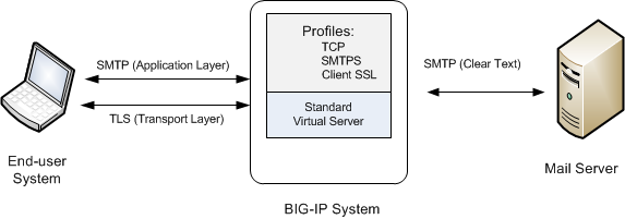
Sample BIG-IP configuration for SMTP traffic with STARTTLS activation
About iSession profiles
The iSession™ profile tells the system how to optimize traffic. Symmetric optimization requires an iSession profile at both ends of the iSession connection. The system-supplied parent iSession profile isession, is appropriate for all application traffic, and other iSession profiles have been pre-configured for specific applications. The name of each pre-configured iSession profile indicates the application for which it was configured, such as isession-cifs.
When you configure the iSession local endpoint on the Quick Start screen, the system automatically associates the system-supplied iSession profile isession with the iSession listener isession-virtual it creates for inbound traffic.
You must associate an iSession profile with any virtual server you create for a custom optimized application for outbound traffic, and with any iSession listener you create for inbound traffic.
Screen capture showing compression settings
The following screen capture shows the pertinent compression settings.
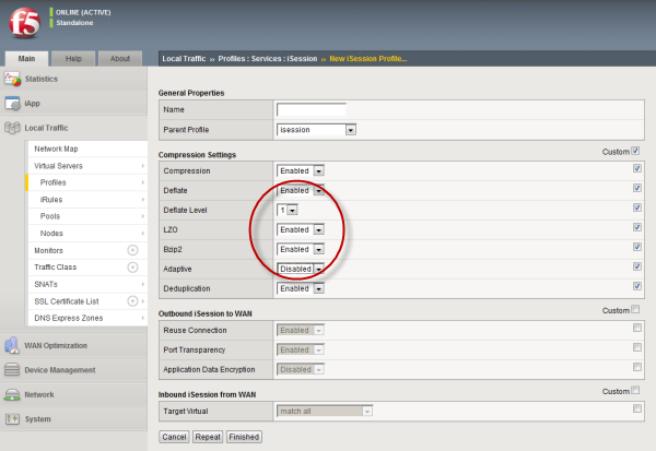
iSession profile screen with compression settings emphasized
Rewrite profiles
For environments that use web servers, you might want your websites to appear differently on the external network than on the internal network. For example, you might want the BIG-IP® system to send traffic destined for www.company.com/usa/ to the internal server usa.company.com instead. Normally, this translation could cause some issues, such as the web server expecting to see a certain host name (such as for name-based virtual hosting) or the web server using the internal host name when sending a redirect to client systems.
You can solve these problems by configuring a Rewrite profile, which causes the BIG-IP system to act as a reverse proxy server. As a reverse proxy server, the BIG-IP system offloads the URI translation function from web servers enabled with features such as Apache's ProxyPass module. With a Rewrite profile, the BIG-IP system can perform URI scheme, host, port, and path modifications as HTTP traffic passes through the system. The feature also provides reverse translation for the Location, Content-Location, and URI headers in the server response to the client.
A typical use of a reverse proxy server is to grant Internet users access to application servers that are behind a firewall and therefore have private IP addresses and unregistered DNS entries.
About URI translation
You can configure the BIG-IP® system to perform URI translation on HTTP requests. Suppose that a company named Siterequest has a website www.siterequest.com, which has a public IP address and a registered DNS entry, and therefore can be accessed from anywhere on the Internet.
Furthermore, suppose that Siterequest has two application servers with private IP addresses and unregistered DNS entries, inside the company's firewall. The application servers are visible within the internal network as appserver1.siterequest.com and appserver2.siterequest.com.
Because these servers have no public DNS entries, any client system that tries to access one of these servers from outside the company network receives a no such host error.
As the illustration shows, you can prevent this problem by configuring the BIG-IP system to act as a reverse proxy server:
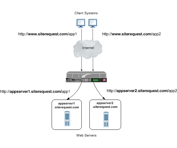
The BIG-IP system as a reverse proxy server for URI translation
In the example, the company Siterequest has decided to enable Web access to the internal application servers, without exposing them to the Internet directly. Instead, the company has integrated the servers with the web server siterequest.com so that http://www.siterequest.com/sales is mapped internally to http://appserver1.siterequest.com/sales, and http://siterequest.com/marketing is mapped internally to http://appserver2.example.com/marketing. This is a typical reverse-proxy configuration.
To configure the BIG-IP system to perform this translation, you create a Rewrite profile and configure one or more URI rules. A URI rule specifies the particular URI translation that you want the BIG-IP system to perform. Specifically, a URI rule translates the scheme, host, port, or path of any client URI, server URI, or both. A URI rule also translates any domain and path information in the Set-Cookie header of the response when that header information matches the information in the URI rule.
Rules for matching requests to URI rules
The BIG-IP® system follows these rules when attempting to match a request to a URI rule:
- A request does not need to match any entry. That is, if no entries match and there is no catch-all entry, then the Rewrite profile has no effect.
- Each request matches one entry only, which is the entry with the most specific host and path.
- If multiple entries match, then the BIG-IP system uses the entry with the deepest path name on the left side of the specified mapping.
- The BIG-IP system matches those requests that contain host names in URIs before matching requests that do not contain host names in URIs.
- The BIG-IP system processes the specified entries in the mapping from most-specific to least-specific, regardless of the order specified in the actual Rewrite profile.
About URI Rules
When creating a URI rule, you must specify the client and server URIs in these ways:
- When the URI is a path prefix only, the path must be preceded by and followed by a /, for example, /sales/.
- When the URI contains more than the path prefix (such as, a host), the URI must also contain a scheme and must be followed by a /, for example, http://www.siterequest/sales/.
About Set-Cookie header translation
A URI rule automatically performs translation on any domain and path information in the Set-Cookie header of a response when that header information matches the information in the URI rule.
When the Set-Cookie header information that you want the BIG-IP® system to translate does not match the information in an existing URI rule, you can create a separate Set-Cookie rule to perform this translation. You need to create a Set-Cookie rule only when the header information does not match the information specified in an existing URI rule.
The specific parts of the Set-Cookie header that you can specify for translation are:
- Client domain
- Client path
- Server domain
- Server path
You can specify that the BIG-IP system translate all of this information or a subset of this information, depending on your needs.
XML profiles
You can use the BIG-IP® system to perform XML content-based routing whereby the system routes requests to an appropriate pool, pool member, or virtual server based on specific content in an XML document. For example, if your company transfers information in XML format, you could use this feature to examine the XML content with the intent to route the information to the appropriate department.
You can configure content-based routing by creating an XML profile and associating it with a virtual server. In the XML profile, define the matching content to look for in the XML document. Next, specify how to route the traffic to a pool by writing simple iRules®. When the system discovers a match, it triggers an iRule event, and then you can configure the system to route traffic to a virtual server, a pool, or a node.
The following example shows a simple XML document that the system could use to perform content-based routing. It includes an element called FinanceObject used in this implementation.
<soapenv:Envelope xmlns:xsi="http://www.w3.org/2001/XMLSchema-instance"
xmlns:xsd="http://www.w3.org/2001/XMLSchema"
xmlns:soapenv="http://schemas.xmlsoap.org/soap/envelope/"
xmlns:eai="http://192.168.149.250/eai_enu/"
xmlns:soapenc="http://schemas.xmlsoap.org/soap/encoding/">
   <soapenv:Header/>
   <soapenv:Body>
     <eai:SiebelEmployeeDelete
soapenv:encodingStyle="http://schemas.xmlsoap.org/soap/encoding/">
             <FinanceObject xsi:type="xsd:string">Route to Financing</FinanceObject>
             <SiebelMessage xsi:type="ns:ListOfEmployeeInterfaceTopElmt"
xmlns:ns="http://www.siebel.com/xml">
                   <ListOfEmployeeInterface xsi:type="ns:ListOfEmployeeInterface">
                         <SecretKey>123456789</SecretKey>
                                  <Employee>John</Employee>
                                  <Title>CEO</Title>
                   </ListOfEmployeeInterface>
             </SiebelMessage>
     </eai:SiebelEmployeeDelete>
   </soapenv:Body>
  </soapenv:Envelope>
SPDY profiles
You can use the BIG-IP® Local Traffic Manager™ SPDY (pronounced "speedy") profile to minimize latency of HTTP requests by multiplexing streams and compressing headers. When you assign a SPDY profile to an HTTP virtual server, the HTTP virtual server informs clients that a SPDY virtual server is available to respond to SPDY requests.
When a client sends an HTTP request, the HTTP virtual server manages the request as a standard HTTP request. It receives the request on port 80, and sends the request to the appropriate server. When the server provides a response, the BIG-IP system inserts an HTTP header into the response (to inform the client that a SPDY virtual server is available to handle SPDY requests), compresses and caches it, and sends the response to the client.
A client that is enabled to use the SPDY protocol sends a SPDY request to the BIG-IP system, the SPDY virtual server receives the request on port 443, converts the SPDY request into an HTTP request, and sends the request to the appropriate server. When the server provides a response, the BIG-IP system converts the HTTP response into a SPDY response, compresses and caches it, and sends the response to the client.
Summary of SPDY profile functionality
By using the SPDY profile, the BIG-IP Local Traffic Manager system provides the following functionality for SPDY requests.
- Creating concurrent streams for each connection.
- You can specify the maximum number of concurrent HTTP requests that are accepted on a SPDY connection. If this maximum number is exceeded, the system closes the connection.
- Limiting the duration of idle connections.
- You can specify the maximum duration for an idle SPDY connection. If this maximum duration is exceeded, the system closes the connection.
- Enabling a virtual server to process SPDY requests.
- You can configure the SPDY profile on the virtual server to receive both HTTP and SPDY traffic, or to receive only SPDY traffic, based in the activation mode you select. (Note that setting this to receive only SPDY traffic is primarily intended for troubleshooting.)
- Inserting a header into the response.
- You can insert a header with a specific name into the response. The default name for the header is X-SPDY.
SPDY profile settings
This table provides descriptions of the SPDY profile settings.
| Setting | Default | Description |
|---|---|---|
| Name | Type the name of the SPDY profile. | |
| Parent Profile | spdy | Specifies the profile that you want to use as the parent profile. Your new profile inherits all settings and values from the parent profile specified. |
| Concurrent Streams Per Connection | 10 | Specifies how many concurrent requests are allowed to be outstanding on a single SPDY connection. |
| Connection Idle Timeout | 300 | Specifies how many seconds a SPDY connection is left open idly before it is closed. |
| Activation Mode | NPN | Specifies how a connection is established as a SPDY connection. The value NPN specifies that the Transport Layer Security (TLS) Next Protocol Negotiation (NPN) extension determines whether the SPDY protocol is used. Clients that use TLS, but only support HTTP will work as if SPDY is not present. The value Always specifies that all connections must be SPDY connections, and that clients only supporting HTTP are not able to send requests. Selecting Always in the Activation Mode list is primarily intended for troubleshooting. |
| Insert Header | Disabled | Specifies whether an HTTP header that indicates the use of SPDY is inserted into the request sent to the origin web server. |
| Insert Header Name | X-SPDY | Specifies the name of the HTTP header controlled by the Insert Header Name setting. |
| Protocol Versions | All Versions Enabled | Used only with an Activation Mode selection of NPN, specifies the protocol and protocol version (http1.1, spdy2, spdy3, or All Version Enabled) used in the SPDY profile. The order of the protocols in the Selected Versions Enabled list ranges from most preferred (first) to least preferred (last). Adding http1.1 to the Enabled list allows HTTP1.1 traffic to pass. If http1.1 is not added to the Enabled list, clients that do not support http1.1 are blocked. Clients typically use the first supported protocol. At least one SPDY version must be included in the Enabled list. |
| Priority Handling | Strict | Specifies how the SPDY profile handles priorities of concurrent streams within the same connection. Selecting Strict processes higher priority streams to completion before processing lower priority streams. Selecting Fair enables higher priority streams to use more bandwith than lower priority streams, without completely blocking the lower priority streams. |
| Receive Window | 32 | Specifies the receive window, which is SPDY protocol functionality that controls flow, in KB. The receive window allows the SPDY protocol to stall individual upload streams when needed. This functionality is only available in SPDY3. |
| Frame Size | 2048 | Specifies the size of the data frames, in bytes, that the SPDY protocol sends to the client. Larger frame sizes improve network utilization, but can affect concurrency. |
| Write Size | 16384 | Specifies the total size of combined data frames, in bytes, that the SPDY protocol sends in a single write function. This setting controls the size of the TLS records when the SPDY protocol is used over Secure Sockets Layer (SSL). A large write size causes the SPDY protocol to buffer more data and improves network utilization. |
SOCKS profiles
You can use the BIG-IP® Local Traffic Manager™ SOCKS profile to configure the BIG-IP system to handle proxy requests and function as a gateway. By configuring browser traffic to use the proxy, you can control whether to allow or deny a requested connection. To implement the profile, you must associate it with a virtual server.
- Protocol Versions
- You can specify one or more versions of SOCKS.
- Socks4 indicates protocol support for SOCKS version 4.
- Socks4A indicates protocol support for SOCKS 4A, which adds host name support to version 4.
- Socks5 specifies protocol support for SOCKS version 5, which includes host name and IPv6 support.
- DNS Resolver
- You must specify a DNS resolver to use for DNS inquiries handled by the virtual servers associated with this profile. If no DNS resolver exists on the system, you can create one at .
- Route Domain
- You can specify a route domain to be used for outbound connect requests.
- Tunnel Name
- You must specify a tunnel that is used for outbound connect requests, enabling other virtual servers to receive connections initiated by the proxy service. A pre-configured tunnel socks-tunnel is available.
- Default Connect Handling
- You can specify the behavior of the proxy service when handling outbound requests.
- Enabled (checked) indicates that the proxy service delivers outbound requests directly, regardless of the presence of listening servers.
- Disabled (check box cleared) indicates that the proxy service delivers outbound requests only if another virtual server is listening on the tunnel for the requested outbound connection. With this setting, virtual servers are required, and the system processes the outbound traffic before it leaves the device.
FIX profiles
The BIG-IP® system Local Traffic Manager™ (LTM®) FIX profile provides you with the ability to use Financial Information eXchange (FIX) protocol messages in routing, load balancing, persisting, and logging connections. The BIG-IP system uses the FIX profile to examine the header, body, and footer of each FIX message, and then process each message according to the parameters that it contains.
The BIG-IP system supports FIX protocol versions 4.2, 4.4, and 5.0, and uses the key-value pair FIX message format.
About FIX profile tag substitution
The BIG-IP® system's FIX profile provides options for how the FIX messages should be parsed. Once configured, the BIG-IP system compares the FIX profile's Mapping List Sender value (SenderCompID) with the value received in the client message. If the values match, then the BIG-IP system provides tag substitution as defined by the data group definition in the corresponding mapping list.
Example
Two or more clients can define a FIX tag differently. On the BIG-IP server side, you can define a dictionary for each client that maps a client tag to a server tag. For example, a server might use 20001 for an analyst's average price target, and 20002 as a client twitter feed name. Then, in the dictionary for the first client, the tag 10001 is mapped to 20001, and, for the second client, the tag 30001 is mapped to 20001.
About steering traffic using the FIX profile
The BIG-IP® system's FIX profile can direct, or steer, FIX messages to a destination pool in accordance with the FIX login message that it receives, and the configured iRules®. Once a pool member is selected, which is only required one time for a connection, all messages in the same FIX session are forwarded, or persisted, to that pool member.
About validating FIX messages
The BIG-IP® system validates each Financial Information eXchange (FIX) protocol message, allowing and denying transmission accordingly. If a FIX message is valid, the BIG-IP system allows transmission, triggers the FIX_MESSAGE iRule event, and optionally logs the message. If a FIX message is invalid, the BIG-IP system logs the error, and either disallows transmission or drops the connection, as configured by the profile.
The BIG-IP system provides two types of parsing validation: full parsing validation and quick parsing validation.
Full Parsing Validation
When full parsing validation is applied, all fields are validated.
Quick Parsing Validation
When quick parsing validation is applied, the following fields are validated.
- The first three fields: 8 (BeginString), 9 (BodyLength), and 35 (MsgType).
- The last field.
- Field 49 (SenderCompID).
- Fields requested by an iRule tag query command.
- Fields in the message that precede the fields requested by an iRule tag query command.
For example, consider the following message: 8=FIX.4.2|9=100|35-A|600=X|700=Y|800=Z.... In this example, the first three fields are always parsed: 8, 9, and 35. If the iRule command FIX::tag 700 runs, then the fields preceding 700 in the example are parsed, specifically 600 (in addition to the first three fields).
The following table describes the different types of quick parsing validation that the BIG-IP system provides.
| FIX Message | Description | Quick Parsing Validation | Example |
|---|---|---|---|
| Message sequence no <num> from <senderCompID> error: There is no = in the field starting at byte <byte offset of the field> | Field is not in the format of tag=val. | This error is partially checked when using quick parsing validation. | 35=A;123xyz;. The second field is missing an = sign. |
| Message sequence no <num> from <senderCompID> error: the field starting at byte <byte offset of the field> has invalid tag | The tag is not an integer. | This error is partially checked when using quick parsing validation. | 35=A;abc=xyz;. The tag abc in the second field is not an integer. |
| Message sequence no <num> from <senderCompID> error: there is no value found in the field starting at byte <byte offset of the field> | A value is missing. | This error is partially checked when using quick parsing validation. | 35=A;50=;. The second field is missing a value. |
| The first (second, third) tag should be 8 (9, 35), but get <wrong value> from < senderCompID> | The first three tags are not 8, 9, and 35. | This error is fully checked when using quick parsing validation. | None. |
| Length mismatch: message sequence no <num> from <senderCompID> should be tag10 after <length> bytes, but encounter <val1 val2> | The length is mismatched. | This error is fully checked when using quick parsing validation. | None. |
| Checksum mismatch: message sequence <num> from <senderCompID> declares checksum as <claimed value>, but calculated checksum from received data is <real value> | The checksum is mismatched. | This error is fully checked when using quick parsing validation. | None. |
| Message from <IP address> is longer than allowed | The message length is greater than 4MB. | This error is fully checked when using quick parsing validation. | None. |
About using SSL encryption for FIX messages
You can configure a virtual server to use client and server SSL encryption with FIX protocol messages, as necessary, for transactions across the Internet, or for compliance purposes.
About logging FIX messages
The BIG-IP® system provides optional logging of each FIX message for auditing purposes. You can log events either locally on the BIG-IP system or remotely, using the BIG-IP system’s high-speed logging mechanism. The recommended way to store logs is on a pool of remote logging servers.
For local logging, the high-speed logging mechanism stores the logs in either the Syslog or the MySQL database on the BIG-IP system, depending on a destination that you define. For remote logging, the high-speed logging mechanism sends log messages to a pool of logging servers that you define.
Video Quality of Experience profiles
The BIG-IP® system's video Quality of Experience (QoE) profile enables you to assess an audience's video session or overall video experience, providing an indication of customer satisfaction. The QoE profile uses static information, such as bitrate and duration of a video, and video metadata, such as URL and content type, in monitoring video streaming. Additionally, the QoE profile monitors dynamic information, such as the variable video downloading rate. By measuring the video playing rate and downloading rate, the user experience can be assessed and defined in terms of a single mean opinion score (MOS) of the video session, and a level of customer satisfaction can be derived. QoE scores are logged in the ltm log file, located in /var/log, which you can evaluate as necessary.
About the video Quality of Experience profile
The BIG-IP® system's video Quality of Experience (QoE) profile enables you to assess an audience's video session or overall video experience, providing an indication of customer satisfaction. The QoE profile uses static information, such as bitrate and duration of a video, and video metadata, such as URL and content type, in monitoring video streaming. Additionally, the QoE profile monitors dynamic information, which reflects the real-time network condition.
By considering both the static video parameters and the dynamic network information, the user experience can be assessed and defined in terms of a single mean opinion score (MOS) of the video session, and a level of customer satisfaction can be derived. QoE scores are logged in the ltm log file, located in /var/log, which you can evaluate as necessary.
Note that for QoE to properly process video files, the video web servers must be compliant with supported video MIME types, for example, the following MIME types.
| MIME Type | Suffix |
|---|---|
| video/mp4 | .f4v |
| video/mp4 | .mp4 |
| video/x-flv | .flv |
| video/x-m4v | .m4v |
| video/quicktime | .m4v |
| application/x-mpegURL | .m3u8 |
| video/mp2t | .ts |
About mean opinion score
The video Quality of Experience (QoE) profile provides a mean opinion score (MOS), derived from static and dynamic parameters associated with a video stream. The following table summarizes the resultant values.
| MOS | Quality | Description |
|---|---|---|
| 5 | Excellent | Indicates a superior level of quality, with imperceptible degradation in the video stream. |
| 4 | Good | Indicates an above-average level of quality, with perceptible degradation that is acceptable. |
| 3 | Fair | Indicates an average level of quality, with perceptible degradation that detracts from the video experience. |
| 2 | Poor | Indicates a below-average level of quality, with perceptible degradation that significantly detracts from the video experience. |
| 1 | Bad | Indicates a substandard level of quality, with perceptible degradation that proves to be significantly inferior and potentially unacceptable. |


