Manual Chapter : Use Case 1 Creating a Configuration that Uses SNAT Auto Map

Applies To:

Show Versions Show Versions

BIG-IP AAM

  • 11.6.5, 11.6.4, 11.6.3, 11.6.2, 11.6.1

BIG-IP APM

  • 11.6.5, 11.6.4, 11.6.3, 11.6.2, 11.6.1

BIG-IP GTM

  • 11.6.5, 11.6.4, 11.6.3, 11.6.2, 11.6.1

BIG-IP Link Controller

  • 11.6.5, 11.6.4, 11.6.3, 11.6.2, 11.6.1

BIG-IP LTM

  • 11.6.5, 11.6.4, 11.6.3, 11.6.2, 11.6.1

BIG-IP AFM

  • 11.6.5, 11.6.4, 11.6.3, 11.6.2, 11.6.1

BIG-IP PEM

  • 11.6.5, 11.6.4, 11.6.3, 11.6.2, 11.6.1

BIG-IP ASM

  • 11.6.5, 11.6.4, 11.6.3, 11.6.2, 11.6.1
Manual Chapter

Using SNAT Auto Map

One of the ways that you can set up all-active clustering of BIG-IP devices is through the use of SNAT Auto Map. This example includes an ECMP-enabled router on the BIG-IP external network and a load balancing pool on the internal network. Each device in the device group has the same virtual IP address and provides a unique, static self IP address for the next-hop route to the virtual server. Furthermore, by enabling SNAT Auto Map on the virtual server, each server response returns through the originating device by way of the unique self IP address on its way back to the client.

This illustration shows an example of this configuration.

BIG-IP system clustering using ECMP 
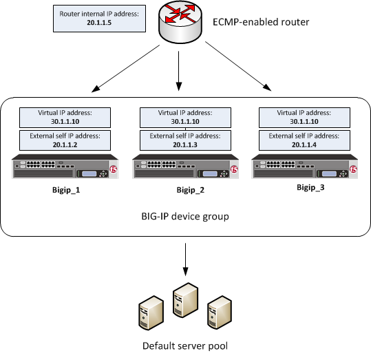
BIG-IP system clustering using ECMP with SNAT Auto Map

Creating a load balancing pool

You can create a load balancing pool to efficiently distribute the load on your server resources. A load balancing pool is a logical representation of the set of servers grouped together on the network to process traffic. After you synchronize the configuration later to the other BIG-IP devices in the device group, the same load balancing pool is configured on all device group members.
Note: You perform this task on only one device in the device group. You will later synchronize this configuration to the other devices in the device group.
  1. On the Main tab, click Local Traffic > Pools. The Pool List screen opens.
  2. Locate the Partition list in the upper right corner of the BIG-IP Configuration utility screen, to the left of the Log out button.
  3. From the Partition list, select the partition in which you want to create local traffic objects.
  4. Click Create. The New Pool screen opens.
  5. In the Name field, type a unique name for the pool.
  6. For the Health Monitors setting, in the Available list, select a monitor type, and click << to move the monitor to the Active list.
    Tip: Hold the Shift or Ctrl key to select more than one monitor at a time.
  7. From the Load Balancing Method list, select how the system distributes traffic to members of this pool. The default is Round Robin.
  8. For the Priority Group Activation setting, specify how to handle priority groups:
    • Select Disabled to disable priority groups. This is the default option.
    • Select Less than, and in the Available Members field type the minimum number of members that must remain available in each priority group in order for traffic to remain confined to that group.
  9. Using the New Members setting, add each resource that you want to include in the pool:
    1. In the Node Name field, type a name for the node portion of the pool member. This step is optional.
    2. In the Address field, type an IP address. This address will reside on the internal subnet of the BIG-IP devices.
    3. In the Service Port field, type a port number, or select a service name from the list.
    4. In the Priority field, type a priority number. This step is optional.
    5. Click Add.
  10. Click Finished.
The load balancing pool appears in the Pools list.

Creating a virtual server

You perform this task to provide a destination for application traffic coming into the BIG-IP system from an ECMP-enabled router on the network. After you synchronize the configuration later to the other devices in the device group, the same virtual server is configured on all of the BIG-IP devices in the device group.
Note: You perform this task on only one device in the device group. You will later synchronize this configuration to the other devices in the device group.
  1. On the Main tab, click Local Traffic > Virtual Servers. The Virtual Server List screen opens.
  2. Locate the Partition list in the upper right corner of the BIG-IP Configuration utility screen, to the left of the Log out button.
  3. From the Partition list, select the partition in which you want to create local traffic objects.
  4. Click the Create button. The New Virtual Server screen opens.
  5. In the Name field, type a unique name for the virtual server.
  6. From the Type list, select Standard.
  7. In the Destination Address field, type the IP address in CIDR format. The supported format is address/prefix, where the prefix length is in bits. For example, an IPv4 address/prefix is 10.0.0.1 or 10.0.0.0/24, and an IPv6 address/prefix is ffe1::0020/64 or 2001:ed8:77b5:2:10:10:100:42/64. When you use an IPv4 address without specifying a prefix, the BIG-IP system automatically uses a /32 prefix.
    Note: This address must be on a separate network available only through routing (instead of through a directly-connected network).
    In our example, this address is 30.1.1.10.
  8. In the Service Port field, type a port number or select a service name from the Service Port list.
  9. From the Source Address Translation list, select Auto Map.
  10. In the Resources area of the screen, from the Default Pool list, select the relevant pool name.
  11. Configure any other settings as needed.
  12. Click Finished.
The virtual server appears in the list of existing virtual servers on the Virtual Server List screen.

Confirming virtual address exclusion from a traffic group

You perform this task to confirm that the virtual address is excluded from being a member of any traffic group on a BIG-IP device in the device group. A virtual address inherits its traffic group membership from the partition in which the virtual address resides.
Important: You perform this task on only one device in the device group. You will later synchronize this configuration to the other devices in the device group.
  1. On the Main tab, click Local Traffic > Virtual Servers > Virtual Address List. The Virtual Address List screen opens.
  2. In the Name column, click the virtual IP address that the BIG-IP system created when you created the virtual server. This displays the properties of that virtual address.
  3. For the Traffic Group setting, confirm that the value is set to None.
  4. Click Update.
After you perform this task, the virtual IP address is no longer a member of any traffic group on the BIG-IP device.

Syncing the BIG-IP configuration to the device group

Before you sync the configuration, verify that the devices targeted for config sync are members of a device group and that device trust is established.
This task synchronizes the BIG-IP configuration data from the local device to the devices in the device group. This synchronization ensures that devices in the device group operate properly.
Note: You perform this task on only one device in the device group.
  1. On the Main tab, click Device Management > Overview.
  2. In the Device Groups area of the screen, in the Name column, select the name of the relevant device group. The screen expands to show a summary and details of the sync status of the selected device group, as well as a list of the individual devices within the device group.
  3. In the Devices area of the screen, in the Sync Status column, select the device that shows a sync status of Changes Pending.
  4. In the Sync Options area of the screen, select Sync Device to Group.
  5. Click Sync. The BIG-IP system syncs the configuration data of the selected device in the Device area of the screen to the other members of the device group.
The BIG-IP configuration data is replicated on each device in the device group.

Configuring the BGP protocol

Before performing this task, verify that you have permission to access the Bash shell.

Perform this task when you want to configure the Border Gateway Protocol (BGP) dynamic routing protocol.

Important: You must perform this task locally on each BIG-IP device.
  1. Open a console window, or an SSH session using the management port, on a BIG-IP device.
  2. Log in to the BIG-IP system using your user credentials.
  3. At the Bash command prompt, type imish. This command invokes the IMI shell.
  4. Type enable.
  5. Type configure terminal.
  6. Type the relevant configuration commands.
    Note: See the relevant sample BGP configuration in this document.
  7. Type copy running-config startup-config. The startup configuration file is /config/zebos/rd0/ZebOS.conf.
  8. At the command prompt, type disable.
  9. Type exit.

Sample BGP configuration using SNAT Auto Map

This example shows part of an example of Border Gateway Protocol (BGP) configuration on a BIG-IP device that accepts traffic from an upstream ECMP-enabled router.

router bgp 65001 bgp router-id 20.1.1.2 redistribute kernel route-map f5-to-upstream neighbor 20.1.1.5 remote-as 65000 ! ip prefix-list RHI-routes seq 5 permit 30.1.1.10/32 ! route-map f5-to-upstream permit 10 match ip address prefix-list RHI-routes set ip next-hop to 20.1.1.2 primary ! line con 0 login line vty 0 39 login ! end
Configuration entry Description
bgp router-id 20.1.1.2 The bgp router-id value is the self IP address for the external VLAN on device Bigip_1. This address must be unique within the BGP configuration on each BIG-IP device in the device group.
neighbor 20.1.1.5 The neighbor value is the IP address of the ECMP-enabled router. You must repeat the neighbor statement for each upstream router associated with a BIG-IP device. These neighbor statements are the same within the BGP configuration on each BIG-IP device in the device group.
ip prefix-list The ip prefix-list entry specifies that the virtual IP address 30.1.1.10/32 is allowed to be advertised.
set ip next-hop 20.1.1.2 The set ip next-hop value is the self IP address for the external VLAN on device Bigip_1. This next-hop address is used for traffic that is destined for the virtual IP address and potentially the specified SNAT pool address. This address must be unique within the BGP configuration on each BIG-IP device in the device group.

Implementation result

After following the instructions in this implementation, you now have a three-member BIG-IP device group, where the same virtual server resides on each device, and each device is configured for dynamic routing using the Border Gateway Protocol (BGP). Also, the external self IP address that you created on each device is configured to allow the upstream ECMP-enabled router to send traffic through port 179 on each BIG-IP device.

With this configuration, when application traffic comes through the ECMP-enabled router, the router can use an algorithm to choose the best equal-cost path to any one of the BIG-IP devices in the device group. If any BIG-IP device becomes unavailable, the ECMP algorithm causes the ECMP-enabled router to forward that traffic to another device in the device group. Furthermore, each BIG-IP device has an administrative partition whose local traffic objects are synchronized to the devices in the Sync-Only device group. All devices in the device group use the default load balancing pool to process application traffic.